Page 14/24
Operating Instructions
BA 7020
Technical specifications subject to change without notice
Copyright according to ISO 16016
6.3 Details on DIP switches:
DIP 1 and DIP 2:
are interpreted together
DIP 1: 0 = voltage →
DIP 2: 0 = 0-10 V or 1 = 2-10 V.
DIP 1: 1 = current →
DIP 2: 0 = 0-20 mA or 1 = 4-20 mA.
Attention
Either a voltage source can be connected to the U-terminal or a current source to the I-terminal.
Never connect both at the same time.
DIP 3:
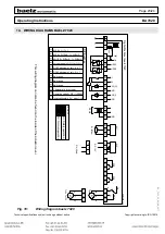
DIP switch 3 configures the analogue outputs AO1 and AO2 (see wiring diagram, chapter
10). DIP switch 3
defines the scaling of the two analogue outputs. When DIP 3 = 0, AO1 is set to 0-10 V and AO2 to 0-20 mA (ex-
works setting), when DIP 3 = 1, AO1 is set to 2-10 V and AO2 to 4-20 mA. In Modbus mode AO1 and AO2 can be
configured separately.
Using 2-10 V / 4-20 mA enables clear identification of a loss of signal (= 0 V / 0 mA).
DIP 4:
DIP switch 4 changes the direction of operation of the actuator.
The direction of operation can only be changed if the unit has been initialized. Until the unit has been initialized,
the following setting applies: Valve closed when actuator spindle extended.
There can also be no change in the direction of operation during an initialisation run, whether or not the unit was
already initialized before starting the current initialisation run.
The direction of operation must not be confused with heating/cooling! Heating in standard mode is carried out with
DIP switches 7, 8 and 9 set to "0". Cooling in standard mode is carried out with DIP switches 7, 8 and 9 set to "1".
Split-range can be combined with heating in standard mode, but not with cooling. In Modbus mode, split-range can
be combined with both heating and cooling.
DIP 5:
Saves the current position as switching position "2EZ-1" when switched from 0 to 1. No function is assigned
to switching from 1 to 0. Even if DIP 5 is left in position 1 when the 7020 positioner is switched on, the current
position will not be saved.
DIP 6:
Saves the current position as switching position "2EZ-2" when switched from 0 to 1. No function is assigned
to switching from 1 to 0. Even if DIP 6 is left in position 1 when the 7020 positioner is switched on, the current
position will not be saved.
DIP 7, DIP 8 and DIP 9:
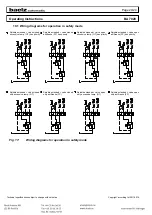
These three DIP switches work together to define the split range function at analogue input 2 (AI2), see Fig.
7.
DIP 10:
An actuator characteristic can be used indirectly to change a valve characteristic. If, for example, the valve has an
equal percentage characteristic, an inverse equal percentage actuator characteristic can be used to generate a
resulting linear characteristic, see Fig. 9.
The actuator characteristic (DIP 10) can also be combined with the characteristics which can be selected using
DIPs 7, 8 and 9 (e.g. split range). The microcontroller first processes the characteristic defined by DIPs 7, 8 and 9
and subsequently the characteristic defined by DIP 10.
In Modbus mode, two further actuator characteristics can be selected: equal percentage and quadratic inverse
equal percentage.
Tip:


