background image


Page 17


Device manual 

6490B / 6490B-y / 6590B 

W. Bälz & Sohn GmbH & Co.  Koepffstraße 5  D-74076  Heilbronn  Telefon (07131) 1500-0  Telefax (07131) 1500-21


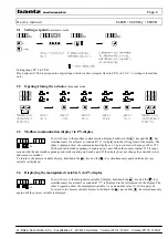
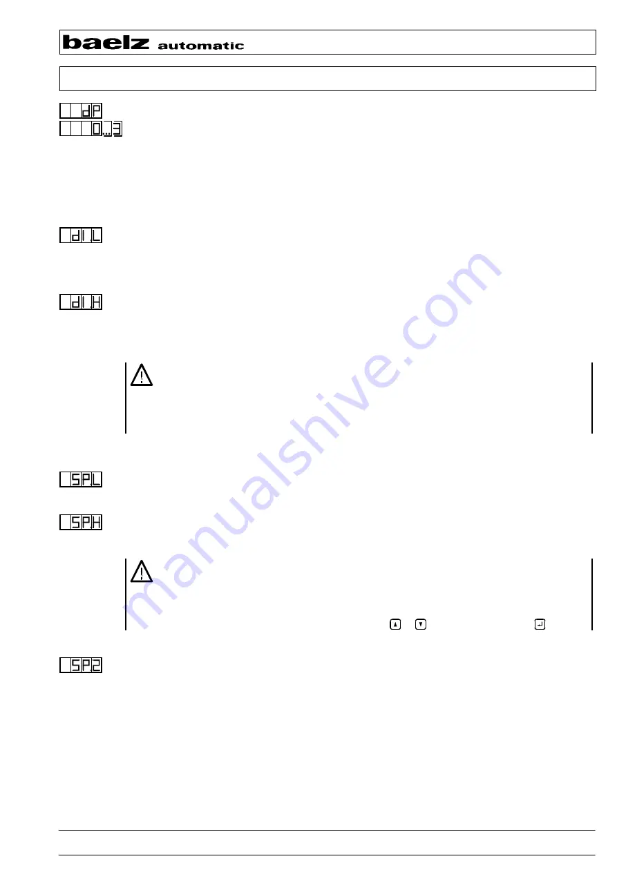
3.8  Decimal point for LED displays


dP


Selection: 

0  Display without decimal point: #### 

2  Display with 2 decimals: ##.## 


1  Display with decimal point (1 decimal): ###.# 

3  Display with 3 decimals: #.### 


After any change of the decimal point the process variable display PV has to be rescaled (see 3.9 dI.L, dI.H). 
By changing the decimal point, several other inputs of the configuration level are concerned. Because of the 
high degree of accuracy of some inputs approximation errors may be possible. 


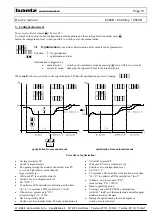
3.9  Scaling the process variable display PV


dI.L, dI.H


Display low: enter zero point of the measuring range. 
Defines the starting point for the PV indication related to the measuring range whereat dI.L < dI.H. 
Setting range (depending on dP):  -999 ... 9999 [phys. units] at dP = 0 

-0.999 ... 9.999 [phys. units] at dP = 3. See also 3.8 dP. 

Standard value: 

0

°C and  

32

°F  respectively 


Display high: enter final point of the measuring range. 
Defines the final point for the PV indication related to the measuring range whereat dI.H > dI.L  
Setting range (depending on dP):  -999 ... 9999 [phys. units] at dP = 0 

-0.999 ... 9.999 [phys. units] at dP = 3. See also 3.8 dP. 

Standard value: 

300

°C and  

572

°F  respectively 


- When changing dI.L or dI.H, all values entered as physical units are rescaled expressed as 

percentage 

- When a Pt100 sensor is used, dI.L and dI.H have to correspond to the Pt100 measuring range of the 

device (see type plate) 
baelz 6490B / 6490B-y / 6590B - 2.4 - ... : dI.L = 0, dI.H = 300 
baelz 6490B / 6490B-y / 6590B - 2.2 - ... : dI.L = 0, dI.H = 400 


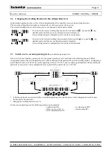
3.10 Setpoint limiting


SP.L, SP.H


Setpoint low:  lowest setpoint which can be set 
Setting range:  dI.L to SP.H [phys. units]  (see also 3.9 dI.L) 
Effective for the setpoint adjustable via front keyboard. 


Setpoint high:  highest setpoint which can be set 
Setting range:  SP.L to dI.H [phys. units]  (see also 3.9 dI.H) 
Effective for the setpoint adjustable via front keyboard. 


- If the range of dI.L/dI.H is changed, SP.L/SP.H is automatically set according to it expressed as 

percentage. 

- When SP.L = SP.H, the setpoint is fixed to this value. Changing the setpoint is not possible.  
- When SP.L > SP.H, only between these two values can be switched via front keyboard. After 

setting SP.L > SP.H, the last entered setpoint is displayed in the operating level. 
The two fixed setpoints can be selected by pressing   or   and adjusted by pressing   . 


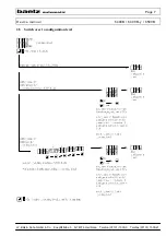
3.11  *Second setpoint SP.2

   at 6x90B(-y) /1 /4 /4-i 

SP.2


Setting range:  dI.L to dI.H [phys. units]  (see also 3.9 dI.L, dI.H) 


When the digital input assigned to SP.2 is active, the corresponding value becomes the actual setpoint 

(see also 3.21-3.25 Assigning the digital inputs). 

* option 

Summary of Contents for mCelsitron 6490B

Page 1: ...0mm Easy operation User defined operating level Digital displays for process variable and setpoint Indication of the manipulated variable at 6490B y with additional bargraph display Control structure...

Page 2: ...SP H 17 3 11 Second setpoint SP 2 at 6x90B y 1 4 4 i SP 2 17 3 12 Setpoint ramp SP r SP r 18 3 13 Ramp direction rA d 18 3 14 Delta setpoint dSP 19 3 15 Delta setpoint description 19 3 16 Process gai...

Page 3: ...ng electrical equipment certain parts of this equipment automatically carry dangerous voltages Failure to observe these instructions could therefore lead to serious injury or material damage Therefore...

Page 4: ...e Digital input OPEN Actuator opens Digital input CLOSE Actuator closes Digital input STOP Actuator persists in its current position Digital input SP 2 To switch over to the second setpoint SP 2 if co...

Page 5: ...En OPEN DI active tunE optimisation running rAMP Setpoint ramp running SP_2 Second setpoint active If one of these functions is active the SP display is alternating between the status display with the...

Page 6: ...counter with a range of 0 to 255 With each valid modbus package it counts up one unit When the counter reaches 255 it wraps around with the next modbus package and starts counting up from 0 again If...

Page 7: ...Page 7 Device manual 6490B 6490B y 6590B W B lz Sohn GmbH Co Koepffstra e 5 D 74076 Heilbronn Telefon 07131 1500 0 Telefax 07131 1500 21 2 5 Switch over to configuration level...

Page 8: ...the next configuration point is displayed Now scrolling inside the configuration level works in forward mode 2 7 Switch over to second operating level user defined operating level How to switch over...

Page 9: ...point 2a Set new value by change in individual steps and respectively 2b Set new value by continuous change with increasing speed and 3 confirm new value within 5s otherwise the previous still effect...

Page 10: ...manual mode optimisation from automatic mode Procedure of optimisation Set target setpoint SP Switch to manual mode By opening closing the actuator the actual value PV is set on a higher lower value...

Page 11: ...ion does not start no alternating tunE and manipulated variable in the setpoint display SP By switching from manual to automatic mode or by changing the setpoint in the automatic mode the optimisation...

Page 12: ...nough Solution Let the optimisation run a couple times until the target setpoint is reached exactly enough The process gain will be defined then by an iterative method what means with every run the pr...

Page 13: ...respond to the first point and the initial setpoint to the other target setpoint of the desired control range see also 2 c b Processes with strongly different time behaviour e g fast heating up slow c...

Page 14: ...of the PID three position step controller Setting range 1s to 255s 3 5 Dead band db No actuating pulses if control deviation is smaller than db Hysteresis db 2 Setting range 0 to 10th part of the scop...

Page 15: ...Alarm at a fixed limit value of PV If AL 1 2 alarm is triggered if the value set at A1 b is reached or exceeded The hysteresis defines a span between alarm state and switching back to normal state Ret...

Page 16: ...of the measuring range phys units 0 to scope of the measuring range phys units at dP 3 AL 1 3 selects Al C and Al C alarm type C see description 3 7c Lower half of the band around the setpoint negativ...

Page 17: ...value 300 C and 572 F respectively When changing dI L or dI H all values entered as physical units are rescaled expressed as percentage When a Pt100 sensor is used dI L and dI H have to correspond to...

Page 18: ...any setpoint change switching over to the second setpoint SP 2 a control function STOP CLOSE OPEN via digital input switching from manual mode to automatic mode 3 13 Ramp direction rA d Setting the d...

Page 19: ...e temperature in the tenter has to drop below the hysteresis of the alarm relay until the control of the burner is released again 1 Then the burner can be moved to its ignition position and be started...

Page 20: ...he STOP command is inactive the controller generates only an OPEN pulse according to the under temperature of 5 K instead of an OPEN pulse according to an under temperature of 15 K Example There is a...

Page 21: ...to the setpoint ramp SP r If the speed of the setpoint ramp SP r gradient is adjusted 0 75 to 0 5 times of the natural temperature rise rate temperature change in fig 1 the setpoint will be reached wi...

Page 22: ...ppressing interference signals and smoothing fast fluctuations of the actual value Formula Tf 0 04 ln input 256 Setting range 0 to 255 At FIL 0 no software filter is active The following assignment ap...

Page 23: ...s 3 24 Assigning the control function STOP to a digital input at 6x90B y 1 4 4 i St d Selection 0 No digital input is selected 1 5 Defines the number of the digital input to activate a STOP command In...

Page 24: ...controlling can be continued with a constant Y display and valve position 3 Mains power has been switched on internal manipulated variable saved manipul variable At mains failure internal manipulated...

Page 25: ...4 4 i S C Selection 0 Operation of the controller via front keyboard and modbus master is possible 1 Operation of the controller is only possible via modbus master except configuration point S C 3 33...

Page 26: ...s 6590B 5 Electrical connection The wiring diagram is located on the backplane 6490B 6490B y and on the top side 6590B of the device respectively The plug type terminals are located on the backplane o...

Page 27: ...Page 27 Device manual 6490B 6490B y 6590B W B lz Sohn GmbH Co Koepffstra e 5 D 74076 Heilbronn Telefon 07131 1500 0 Telefax 07131 1500 21 5 1 Wiring diagram...

Page 28: ...s the corresponding DI state text displayed in the SP display e g StOP CLOS Check voltage supply for digital inputs external switching contacts signal lines and electrical connection Consider the disp...

Page 29: ...f the measuring range Digital inputs high active low n c 0 V DC high 15 V to 24 V DC Displays Two 4 digit 7 segment displays LED red character height 6490B 6490B y 13mm character height 6590B 10mm Ala...

Page 30: ...via digital input DI CLOSE command via digital input DI STOP command via digital input DI Number of alarm relays RS 485 interface modbus RTU mode Standard temp range 2 4 0 C 300 C with 0 1 accuracy Al...

Page 31: ...range phys units at dP 3 Alarm 1 type C lower limit A1 C 0 to scope the of measuring range phys unit at AL 1 3 Hysteresis lower limit for A1 C HY 1 0 to 10th part of the scope of the measuring range...

Page 32: ...al Y position is not saved in case of a mains failure 1 Y bargraph is displayed actuator does not close for the time of the valve actuating time at mains recov internal Y position 0 actual Y position...

Page 33: ...Remarks Second operating level OL 2 0 No second operating level 1 Optimisation 2 Alarm functions and their hysteresis 4 Reserved no function yet 8 Second setpoint SP 2 16 Setpoint ramp SP r Result of...

Reviews: