Page 22
Device manual
6490B / 6490B-y / 6590B
W. Bälz & Sohn GmbH & Co. Koepffstraße 5 D-74076 Heilbronn Telefon (07131) 1500-0 Telefax (07131) 1500-21
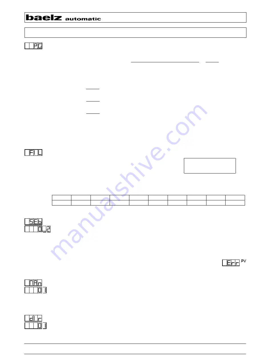
3.16 Process gain P.G
P.G
Setting range: 1% to 255%
Process gain of the controlled system P.G =
Change of the process variable PV
=
∆
PV
∆
Y
Change of the manipulated variable Y
∆
PV [% of the measuring range of PV]
∆
Y [% of the setting range 0-100]
e.g. P.G = 50%:
∆
PV
∆
Y
= 0,5
Changing the valve position
∆
Y for 10% causes a change of the process
variable PV of 5%.
P.G = 100%:
∆
PV
∆
Y
= 1,0
Changing the valve position
∆
Y for 10% causes a change of the process
variable PV of 10%.
P.G = 125%:
∆
PV
∆
Y
= 1,25
Changing the valve position
∆
Y for 10% causes a change of the process
variable PV of 12.5%.
The process gain P.G is required for the optimisation of the control parameters. If P.G is unknown, it is
determined automatically during optimisation (see also 3.1 OPt).
In case of non-linear transfer behaviour of the plant the process gain changes with the working point
(e.g. when controlling different setpoints).
3.17 Measured value filter for the process variable PV
FIL
Software 1st order low-pass filter with adjustable time-constant Tf for
suppressing interference signals and smoothing fast fluctuations of the
actual value.
Formula :
Tf = -0.04/ln(input/256)
Setting range : 0 to 255
At FIL = 0 : no software filter is active
The following assignment applies:
Input:
255 254 252 250 240 230
*
220 200 0
Tf
[s]:
10.22 5.10 2.54 1.69 0.62 0.37 0.26 0.16 off
* standard setting
3.18 Behaviour in case of sensor failure for PV
SE.b
Reaction of the actuator in automatic mode in case of sensor short circuit or sensor break.
Selection: 0 actuator closes
1 actuator opens
2 actuator persists in its current position
In case of a transmitter/sensor failure the error message
Err
(error) appears in the display PV.
Alarm message if alarm A, B or C is configured, independent on the adjusted alarm limit.
After the error is no longer present, the controller automatically returns to the
automatic mode.
3.19 Interlocking the manual/automatic switch over
Man
Selection: 0 Switch over via front keyboard, possible at any time
1 Interlocking the current state, switching to the other mode is not possible
MAn.= -1- in automatic mode: permanent automatic mode
MAn.= -1- in manual mode: permanent manual mode
3.20 Direction of effect of the controller
dIr
Selection: 0 Heating controller: the actuator closes with process variable PV
>
setpoint SP
1 Cooling controller: the actuator opens with process variable PV
>
setpoint SP

