background image

35


DISPL

A

Y DP C240.C

AN

Error

Declaration

Troubleshooting

37

WDT circuit is faulty

Using the BESST tool update the controller to see if 
this resolves the problem. If not, please change the 
controller or contact your supplier.

41

Total voltage from the battery is 
too high

Please change the battery.

42

Total voltage from the battery is 
too low

Please Charge the battery. If the problem still occurs, 
please change the battery.

43

Total power from the battery 
cells is too high

Please change the battery.

44

Voltage of the single cell is too 
high

Please change the battery.

45

Temperature from the battery is 
too high

Please let the pedelec cool down.

If problem still occurs, please change the battery.

46

The temperature of the battery 
is too low

Please bring the battery to room temperature. If the 
problem still occurs, please change the battery.

47

SOC of the battery is too high

Please change the battery.

48

SOC of the battery is too low

Please change the battery.

61

Switching detection defect

1. Check the gear shifter is not jammed.

2. Please change the gear shifter.

62

Electronic derailleur cannot 
release.

Please change the derailleur.

71

Electronic lock is jammed

1. Using the BESST tool update the Display to see if it 
resolves the problem.

2. Change the display if the problem still occurs, 
please change the electronic lock. 

81

Bluetooth module has an error

Using the BESST tool, re-update the software onto 
the display to see if it resolves the problem.

If not, Please change the display.

Summary of Contents for E-SYSTEM

Page 1: ...MANUAL BAFANG E SYSTEM EN EN...

Page 2: ...INHALT Display DP C11 CAN 3 Display DP C240 CAN 21 Motor H300 RM G010 250 D 37 Motor H400B RM G020 250 350 DC 41 Motor H600 RM G370 250 DC 45...

Page 3: ...4 Display 6 1 5 Key Definition 6 1 6 Normal Operation 7 1 6 1 Switching the System On Off 7 1 6 2 Selection of Support Levels 7 1 6 3 Selection mode 7 1 6 4 Headlights backlighting 8 1 6 5 Walk Assist...

Page 4: ...TANT NOTICE If the error information from the display cannot be corrected according to the inst ructions please contact your retailer The product is designed to be waterproof It is highly recommended...

Page 5: ...ndicator Lighting control Brightness setting for backlight Walk assistance Indication of performance support Motor output power indicator Time display for single journeys Kilometer stand including sin...

Page 6: ...e lights are turned on 4 Unit of speed 5 Digital speed display 6 Trip Daily kilometers TRIP Total kilometers ODO Top speed MAX Average speed AVG Rremaining distance RANGE Ener gy Consumption CALORIES...

Page 7: ...st enter the correct password to use the system 1 6 2 Selection of Support Levels When the display is turned on press the or button 0 5S to switch to the support level the lowest level is 0 the highes...

Page 8: ...nce The Walk assistance can only be activated with a standing pedelec Activation Press the button until this symbol appears Next press and hold down the button whilst the symbol is displayed now the W...

Page 9: ...unction is displayed on the display Every 5000 km the display SERVICE is displayed every time This function can be set in the display settings 1 6 7 Battery capacity indicator The battery capacity is...

Page 10: ...n menu or highlight BACK and press 0 5S the button 0 5S to return to the Settings interface 1 7 1 Display Setting Press the or button 0 5S and highlight Display Setting and then briefly press the butt...

Page 11: ...ghlight Brightness in the Display setting menu and then press button 0 5S to select Then with the or button choose between 100 75 50 30 10 Once you have chosen your desired selection press the button...

Page 12: ...Once you have chosen your desired selection press the button 0 5S to save and exit to the Display setting 1 7 1 6 Service Switching the notification on and off Press the or button 0 5S to highlight S...

Page 13: ...ighlight Wheel Size then press the button 0 5S to confirm and view the wheel size To return press the button 0 5S to exit back to the Informa tion This information cannot be changed this is only for i...

Page 14: ...erature b12 Maximum not charging time Hour b04 Total voltage mV b13 Recently not char ging time Hour b06 Average current mA d00 Number of battery cell b07 Remaining capacity mAh d01 Voltage of cell 1...

Page 15: ...orque Info then press the button 0 5S to confirm Now press the or button 0 5S to view Hardware Version or Software Version To return press the button 0 5S to exit back to the Information 1 7 2 7 Error...

Page 16: ...2 Disconnect and reconnect the throttle if still no function please change the throttle 07 Overvoltage protection 1 Remove and re Insert the battery to see if it resolves the problem 2 Using the BESS...

Page 17: ...our supplier 21 Speed sensor Error 1 Restart the system 2 Check that the magnet attached to the spoke is aligned with the speed sensor and that the distance is between 10 mm and 20 mm 3 Check that the...

Page 18: ...ostics test to see if it can pinpoint the problem 3 Change the display to see if the problem is solved 4 Change the EB BUS cable to see if it resolves the problem 5 Using the BESST tool re update the...

Page 19: ...wn If problem still occurs please change the battery 46 The temperature of the battery is too low Please bring the battery to room temperature If the problem still occurs please change the battery 47...

Page 20: ...20...

Page 21: ...Definition 24 2 6 Normal Operation 25 2 6 1 Switching the System On Off 25 2 6 2 Selection of Support Levels 25 2 6 3 Selection Mode 25 2 6 4 Headlights backlighting 26 2 6 5 Walk Assistance 26 2 6 6...

Page 22: ...T NOTICE If the error information from the display cannot be corrected according to the inst ructions please contact your retailer The product is designed to be waterproof It is highly recommended to...

Page 23: ...tem Brightness setting for backlight Indication of performance support Kilometer stand including single trip dis tance total distance and remaining distance BOOST function NOTE it needs the control le...

Page 24: ...4 6 5 1 Headlight indication 2 USB connection indication 3 Battery capacity indication 4 Speed display in real time 5 Assistance level indication 6 Multiple data indication 2 5 KEY DEFINITION Up Down...

Page 25: ...level is Level 0 the highest Level is 5 On the default is Level 1 0 means no power assistance The interface is as following Note if the controller has Boost function can be selected this level with b...

Page 26: ...display backlight headlight are turned off manually they also need to be turned on manually afterwards 2 6 5 Walk Assistance The Walk assistance can only be activated with a standing pedelec Activati...

Page 27: ...speed is not arrived 25km h this function can not be implemented and press button and hold 2S the HMI can powered off 2 6 7 Battery Capacity Indication The percentage of current battery capacity and t...

Page 28: ...t back to the Setting interface 2 7 1 2 Auto Off Set automatic Off time Briefly press or to select Auto Off and briefly press to enter into the item Then select the automatic Off time as OFF 9 8 7 6 5...

Page 29: ...e The riding time TIME average speed AVG and maximum speed MAXS will be reset simultaneously when you reset TRIP 2 7 1 7 Vibration Set the button vibration Briefly press or to select Vibration and bri...

Page 30: ...imit default Press the button 0 5S to exit back to the Information interface 2 7 2 3 Battery Info Briefly press or to select Battery Info and briefly press to enter then briefly press or to view the b...

Page 31: ...ce 2 7 2 5 Ctrl Info Briefly press or to select Ctrl Info and briefly press to enter briefly press or to view Hardware Ver or Software Ver Press the button 0 5S to exit back to the Information interfa...

Page 32: ...2 Disconnect and reconnect the throttle if still no function please change the throttle 07 Overvoltage protection 1 Remove and re Insert the battery to see if it resolves the problem 2 Using the BESS...

Page 33: ...our supplier 21 Speed sensor Error 1 Restart the system 2 Check that the magnet attached to the spoke is aligned with the speed sensor and that the distance is between 10 mm and 20 mm 3 Check that the...

Page 34: ...ostics test to see if it can pinpoint the problem 3 Change the display to see if the problem is solved 4 Change the EB BUS cable to see if it resolves the problem 5 Using the BESST tool re update the...

Page 35: ...own If problem still occurs please change the battery 46 The temperature of the battery is too low Please bring the battery to room temperature If the problem still occurs please change the battery 47...

Page 36: ...36...

Page 37: ...37 H300 RM G010 250 D MOTOR H300 RM G010 250 D CONTENT 3 1 Introduction 38 3 2 Specifications 39 3 2 1 Surface 39 3 2 2 Storage Information 39 3 3 Maintenance 39...

Page 38: ...city and trekking bikes which have been developed for road use The engine is not suitable for sport competitions Identification The following graphic is the identification numbers of the product whic...

Page 39: ...oid storing the pedelec near strong magnetic objects MOTOR H300 RM G010 250 D 3 3 MAINTENANCE Maintenance must be carried out by autho rized personnel with the correct equipment Do not disassemble the...

Page 40: ...40...

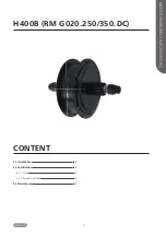
Page 41: ...41 CONTENT H400B RM G020 250 350 DC MOTOR H400B RM G020 250 350 DC 4 1 Introduction 42 4 2 Specifications 43 4 2 1 Surface 43 4 2 2 Storage Information 43 4 3 Maintenance 43...

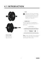
Page 42: ...able for city and trekking bikes which have been developed for road use The engine is not suitable for sport competitions Identification The following graphic is the identification numbers of the prod...

Page 43: ...a ventilated dry room Avoid storing the pedelec near strong magnetic objects 4 3 MAINTENANCE Maintenance must be carried out by autho rized personnel with the correct equipment Do not disassemble the...

Page 44: ...44...

Page 45: ...45 MOTOR H600 RM G370 250 DC CONTENT RM G370 250 DC 5 1 Introduction 46 5 2 Specifications 47 5 2 1 Surface 47 5 2 2 Storage Information 47 5 3 Maintenance 47...

Page 46: ...ity trekking and road bikes which have been developed for road use The engine is not suitable for sport competitions Identification The following graphic is the identification numbers of the product w...

Page 47: ...ilated dry room Avoid storing the pedelec near strong magnetic objects 5 3 MAINTENANCE Maintenance must be carried out by autho rized personnel with the correct equipment Do not disassemble the motor...

Reviews: