Copyright 1999-2009, Barcode Automation, inc.
18
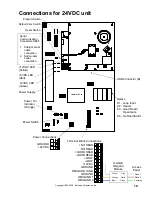
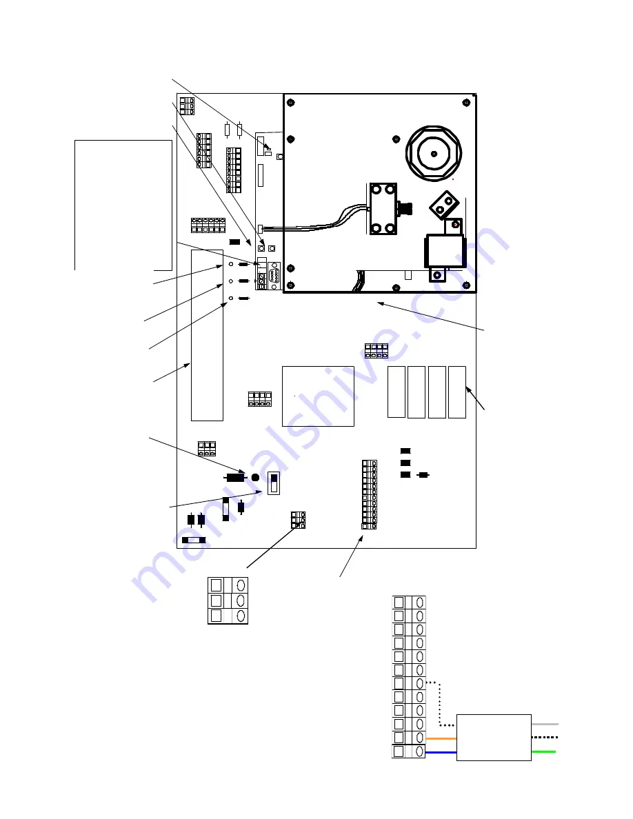
Connections for 24VDC unit
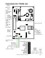
Heater and Fan
GND
Tx
R x
Reset Switch
Default Com Switch
Serial
Communication
Connectors DB9F
1.
Straight serial
cable
connection.
2.
Null modem
serial
connection.
Power Switch
Power On
Indicator
(Orange)
Relays
Power Supply
+12VDC LED
(Yellow)
+5VDC LED
(Red)
-12VDC LED
(Green)
K1 - Loop Input
K2 - Heater
K3 - Good Read/
Open Gate
K4 - No Read/Alarm
Program Switch
USB Connector (B)
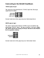
GROUND
NEUTRAL
LINE (HOT)
Power Connections
GROUND
+24VDC
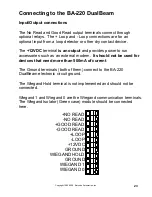
+NO READ
-NO READ
+GOOD READ
-GOOD READ
+LOOP
-LOOP
+12VDC
GROUND
WIEGAND HOLD
GROUND
WIEGAND 1
WIEGAND 0
Terminal Block Connections
Isolated
Wiegand
Module
Gray
White
Green
Blue
Orange
Yellow
Common
Data 0
Data 1
Access
Panel


