background image

Copyright 1999-2009, Barcode Automation, inc. 

General Specifications 


READ TRIGGER 

Continuous Scan 
Loop Detector Input 
 

OPTICAL 

Reading area begins 24” from enclosure and extends out to 72” 
The laser lines are vertical with a fan shaped read area. 


Read area chart 
in inches  
above pavement. 
 
This assumes that 
the center of the 
BA-220 
DualBeam 
window is 54” 
above the 
pavement. 


Reading distance in inches from the body of the  
BA-220 DualBeam. Barcodes will be read in zones A, 

         B, and C  under normal conditions.  Zone B coverage 
         is guaranteed in all reasonable driving conditions. 

6

12

18

24

30

36

42

48

54

60

66

72

78

84

90

96

6

12

84

90

96

60

54

48

66

72

18

24

30

36

42

78

A

B

C

Summary of Contents for BA-220

Page 1: ...CODE READER revised 1 31 2009 800 528 9167 407 327 2177 FAX 407 327 6172 Post Office Box 195268 Winter Springs FL 32719 5268 email Cust Svc Barcode Automation com web page http www Barcode Automation...

Page 2: ...utomation Inc has made every effort to insure that the information in this manual is both accurate and adequate It is recommended in the interest of safety and efficiency that each section be read car...

Page 3: ...ation of this equipment in a residence is likely to cause interference in which case the user at his own expense will be required to take whatever measures necessary to correct the interference CDRH C...

Page 4: ...us radiation or electrical voltages OPTICAL SAFETY Never stare directly into laser beam The laser diode is interlocked with the motor that turns the polygon mirror so that if the motor slows or stops...

Page 5: ...These include Window glass both inside and outside 8 sided gold mirror wheel Polygon Small mirror below gold wheel Polygon Fisheye lens in the silver block below the small mirror Optics should be clea...

Page 6: ...SER DIODE 1 0 MILLIWATT MAX OUTPUT CLASS II LASER PRODUCT CLASS II LASER PRODUCT THIS PRODUCT CONFORMS TO DHHS REGULATION 21 CFR SUBCHAPTER J NOT USER SERVICEABLE CAUTION LASER LIGHT WHEN OPEN DO NOT...

Page 7: ...Installation and Setup Steps 10 Determine where the Reader will be installed 10 What Wiring do I need 13 Typical Installation Illustration 16 Interface Connections for 115VAC unit 17 Interface Connec...

Page 8: ...ypical 60 Watts maximum with heater on CIRCUIT PROTECTION For 115VAC input 2 5A 250V fuse located on mainboard For 24VDC unit 3A resettable PTC located on mainboard ENVIRONMENTAL Operating Temperature...

Page 9: ...read area Read area chart in inches above pavement This assumes that the center of the BA 220 DualBeam window is 54 above the pavement Reading distance in inches from the body of the BA 220 DualBeam...

Page 10: ...the BA 220 DualBeam was not set up for your specific installation at the Factory you will have to configure the Reader after it is mounted in place To do this refer to the Operation and Configuration...

Page 11: ...intended to be used on a 6 curb or concrete mounting pad for a total height of 40 To fabricate a mounting post refer to the appendix for drawings The reader should be mounted close to the edge of the...

Page 12: ...ill be installed In some locations the vehicle drive is very wide as shown in the illustration above In these cases we recommend painting lane lines or stripes to indicate where the vehicle must pass...

Page 13: ...n the gate If access is denied the gate does not open and an optional No Read relay contact will close that can be connected to an indicator or alarm to indicate that access is denied Wiring Needed 2...

Page 14: ...granted the panel opens the gate Wiring Needed Shielded 3 conductor 18 AWG from reader to access control panel for Wiegand communication 3 conductor for AC power connection follow local electrical cod...

Page 15: ...efer to local building code for requirements Communications For RS232 interface Three wires Transmit Receive Ground Minimum 3 conductor shielded cable 18 AWG For Wiegand interface Three wires Wiegand...

Page 16: ...Barcode Automation inc 16 9 34 6 40 24 35 67 Typical Installation Illustration With a 34 mounting post and a 6 curb the BA 220 DualBeam at 24 from the housing can read barcode decals between 36 and 65...

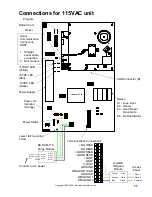
Page 17: ...llow 5VDC LED Red 12VDC LED Green K1 Loop Input K2 Heater K3 Good Read Open Gate K4 No Read Alarm Connect to AC power Lower left mounting screw BA SSM 115 Surge Module Green White Black Green Black Wh...

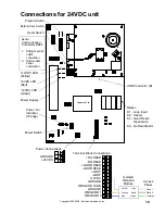
Page 18: ...Indicator Orange Relays Power Supply 12VDC LED Yellow 5VDC LED Red 12VDC LED Green K1 Loop Input K2 Heater K3 Good Read Open Gate K4 No Read Alarm Program Switch USB Connector B GROUND NEUTRAL LINE H...

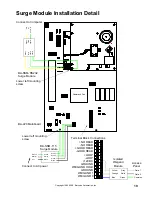
Page 19: ...ack White Green Hot Neutral Ground BA 220 Mainboard Green Gray Yellow Green Yellow Gray Green RX T X Ground BA SSM RS232 Surge Module Lower left mounting screw Connect to Computer NO READ NO READ GOOD...

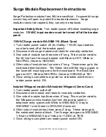
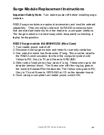
Page 20: ...NEUTRAL Green to GROUND 4 Other side of module has four wires 4 long These wires go to the mainboard terminal block The Green wire with the ring lug goes to the lower left mounting screw for the mainb...

Page 21: ...iagnostics RS232 Surge module BA SSM RS232 Blue Case 1 Turn reader power switch off 2 Disconnect old surge module and retain for warranty validation 3 One side of module has three wires 6 long This mu...

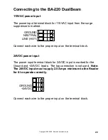
Page 22: ...onnect each wire to the proper input on the terminal block 24VDC power input The power input terminal block for 24VDC input is marked for the Ground and 24VDC leads The top connection is not used Note...

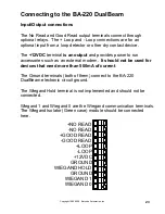
Page 23: ...provides power to run accessories such as an external modem It should not be used for devices that need more than 500mA of current The Ground terminals both of them connect to the BA 220 DualBeam elec...

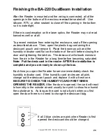
Page 24: ...he door and tightening the latches The desiccant will absorb moisture from the air in the Reader for a long time before becoming saturated Note Put the desiccant in the reader AFTER the installation i...

Page 25: ...When the BA 220 DualBeam is powered on The Main Power indicator should light up The 12VDC LED yellow 5VDC LED red and 12VDC LED green should light up on the mainboard See pages 16 17 The fan should b...

Page 26: ...cted to Wiegand 1 and Wiegand 0 and see if the LED s go off If they do the wiring may be at fault Trace the communication wiring and be sure it is connected properly to the access control equipment Lo...

Page 27: ...cator light The only time you need to wait 1 second between reads is if you have only 1 barcode number to test with As you pass the barcode through the laser line watch the two red LED s Data0 Act and...

Page 28: ...t read reliably through the glass 3 Orient decal with the stripes running horizontal as shown 4 The bottom of the decal should be at least 36 inches above the ground 5 The top of the decal should be n...

Reviews: