12
12
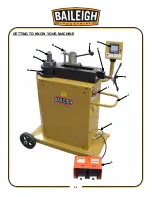
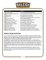
Item Description
Function
A Grease Zerk
For Greasing Main Spindle Bearing
B Main Spindle And Drive Pins
For Supporting The Bend Dies And Driving The Dies
C Center Pin
For Aligning Die Onto Spindle
D Hitch Pin
For Mounting The Counter Die
E Quick Release
For Pivoting Counter Die Away From Bend Die To
Remove Material Quickly
F Numerical Counter
For Indicating Counter Die Position
G Touch Screen Controller
For Programming Bend Data
H 3 Legged Handwheel
For Adjusting Counter Die Position
I
Main Disconnect Switch
For Turning Power On/Off
J Push Handle
For Maneuvering Machine On Its Wheels
K Power Cord
For Connecting To Main Power Source
L Foot Pedal Guard
Protect Against Accidental Operation
M Forward Foot Pedal
Will Operate The Machine In The cw Direction
N Reverse Foot Pedal
Will Operate The Machine In The ccw Direction
GENERAL DESIGN DESCRIPTION
You have made a practical choice in purchasing the RDB-250 Fully Programmable Bending
Machine. It has been carefully built of high quality materials and designed to give many years of
efficient service. The simplicity of design and minimum effort required to operate the machine
contributes towards meeting schedules and producing greater profits.
The RDB-250 is an electric powered “Rotary Draw” bending machine. To bend material, a
bending die and counter die are required. The material is hooked by the bending dies’ hook arm
and is powerfully rotated in the clockwise direction. As the bending die rotates, the counter die
remains stationary, forcing the material to conform to the radius and shape of the bending die.
The RDB-250 Bending Machine you have purchased is built of solid steel ensuring maximum
rigidity. Tongue and groove design with grade 8 bolts throughout provides very high rigidity and
stability.
Throughout this manual are listed various safety-related descriptions for attention. These
matters for attention contain the essential information to the operators while operating, and
maintaining. Failure to follow these instructions may result in great damage to the machine or
injury to the operator.
Summary of Contents for B8085
Page 14: ...11 11 GETTING TO KNOW YOUR MACHINE A B C D E F G H I J K L M N...
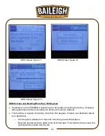
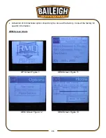
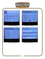
Page 29: ...26 26 OEM Screen Figure 14 OEM Screen Figure 15 OEM Screen Figure 16 OEM Screen Figure 17...
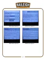
Page 30: ...27 27 OEM Screen Figure 18 OEM Screen Figure 19 OEM Screen Figure 20 OEM Screen Figure 21...
Page 31: ...28 28 OEM Screen Figure 22...
Page 45: ...42 42 INDEX TABLE LAYOUT DIAGRAM OPTIONAL EQUIPMENT...
Page 52: ...49 49 Diagram 1...
Page 53: ...50 50 Diagram 2...
Page 54: ...51 51 PARTS DIAGRAM Base Assembly Parts Diagram...
Page 55: ...52 52 Control Box Parts Diagram...
Page 56: ...53 53 Drive Assembly Parts Diagram...
Page 57: ...54 54 Main Bending Assembly Parts Diagram...
Page 61: ...58 58...

