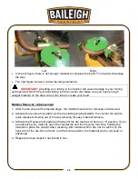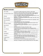
21
21
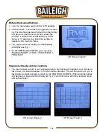
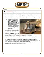
3. After selecting the program touch the RUN button and the program parameters will be
displayed Fig 7.
4. Verify the spindle is clear and ready to perform a dry run or that the die is secure and
material properly loaded.
5. Press and hold the Forward foot pedal down to produce the sample bend.
6. When at the final position, the screen will read, “Bend Done. Release FWD Pedal” and then
"Press REV Pedal to Home”.
7. Press and hold the reverse foot pedal until the spindle reaches "0" degrees.
8. If a second or more bends have been programmed, the Bend # display will change to the
next bend number. This will be the next bend and so on all the way to the last programmed
bend up to bend 10.
9. Reposition or load the material for the next bend.
10. If only 1 bend is programmed, bend 1 will be repeated until the program is exited and a
different program is loaded.
Manual Bend
Manual Operation has two control levels. Manual Mode and Full Manual Mode.
Manual Mode
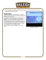
Manual Mode allows for bending to specific angles
with or without springback allowance. Select this
feature to bend manually without the need to create a
program but still be able to atop at a specific angle.
The angle indicator will display the relative bend
angle with the actual degree shown below the dial.
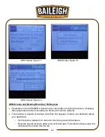
1. On the RMD MAIN SCREEN, chose "MANUAL
MODE" Fig 1.
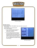
2. Press on the Angle box to open the key pad (Fig.
4) and then enter the angle.
3. If a spring back is required, press on the Spring
box to open the key pad (Fig. 4) and then enter
the amount of spring back angle.
4. With the arrow keys a bend speed from 1-6 can be
selected, 1 or 2 recommended. The closer to bend capacity, the slower the speed setting
should be.
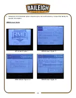
OP Screen Figure 8
Summary of Contents for B8085
Page 14: ...11 11 GETTING TO KNOW YOUR MACHINE A B C D E F G H I J K L M N...
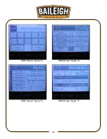
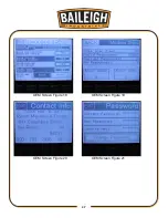
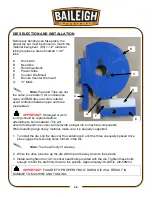
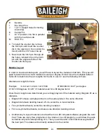
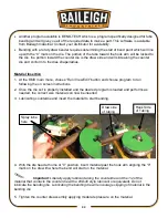
Page 29: ...26 26 OEM Screen Figure 14 OEM Screen Figure 15 OEM Screen Figure 16 OEM Screen Figure 17...
Page 30: ...27 27 OEM Screen Figure 18 OEM Screen Figure 19 OEM Screen Figure 20 OEM Screen Figure 21...
Page 31: ...28 28 OEM Screen Figure 22...
Page 45: ...42 42 INDEX TABLE LAYOUT DIAGRAM OPTIONAL EQUIPMENT...
Page 52: ...49 49 Diagram 1...
Page 53: ...50 50 Diagram 2...
Page 54: ...51 51 PARTS DIAGRAM Base Assembly Parts Diagram...
Page 55: ...52 52 Control Box Parts Diagram...
Page 56: ...53 53 Drive Assembly Parts Diagram...
Page 57: ...54 54 Main Bending Assembly Parts Diagram...
Page 61: ...58 58...

