31
31
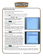
7. Press the
Enter key. This will enter the value into the YP line and move the
highlight to the next line. The DX line.
8. Enter the value desired for the back-gauge to retract away from the work piece (DX). 0 (zero)
will keep the back gauge in position for the entire bend. This value will be displayed in the
bottom line of the screen.
9. Press the
Enter key. This will enter the value into the DX line and move the
highlight to the next line. The HT line.
10. Enter the value needed for the Hold Time (HT). Generally, start with a value of 1.5 seconds
and fine tune the number with experience for the specific bend and material. This value will
be displayed in the bottom line of the screen. This is a time value that starts when the down
travel contact block activates the down travel limit switch. This value must be long enough
for the ram to reach the full down stroke and cause the hydraulic system to reach pressure
relief for at least 0.1 second.
11. Press the
Enter key. This will enter the value into the HT line and move the
highlight to the next line. The DLY line.
12. Enter the value, if needed, for a delay to occur before the back-gauge will retract away from
the work piece. This will allow the punch to move deeper into the bend before the back-
gauge move back away from the work piece. This value will be displayed in the bottom line
of the screen.
13. Press the
Enter key. This will enter the value into the DLY line and move the
highlight to the next line. The PP line.
14. Enter the value for the number of parts desired (PP). Enter 0 (zero) if no piece count is
needed. This number could be the number of pieces for the complete job, or how many parts
fit in a container, or some other value that creates a counting point. When this value is
reached during operation, the controller will automatically switch from the Run to Stop. Press
the green Start/Run key to reset the count and count the next set of parts. This value will be
displayed in the bottom line of the screen.
15. Press the
Enter key. This will enter the value into the PP line and move the
highlight to the next line. The CP line.
16. Enter 0 (zero) to clear the bend count if the PP line is 0 (zero). If the PP has a programed
value, do not change this line. This value will be displayed in the bottom line of the screen.
a. The CP line is a bend counter line. If 0 (zero) is entered for the PP value, the CP line
will continue to count each bend cycle as one bend. If the PP line has a value, the CP
number will count down from the programmed value to 0 (zero) to complete the
counted parts.
Summary of Contents for BP-3305CNC
Page 3: ...Back Gauge Adjustment 48 BEND TONNAGE CHART 50...
Page 17: ...14 14...
Page 21: ...18 18 GETTING TO KNOW YOUR MACHINE A B M L K D C E F G I H J I G...
Page 22: ...19 19 N S T U X V O Q P R W...
Page 44: ...41 41 INCLUDED LOWER AND UPPER TOOLING Lower Tool Die Upper Tool Punch...
Page 54: ...51 51 NOTES...
Page 55: ...52 52 NOTES...


