background image


37 

37 

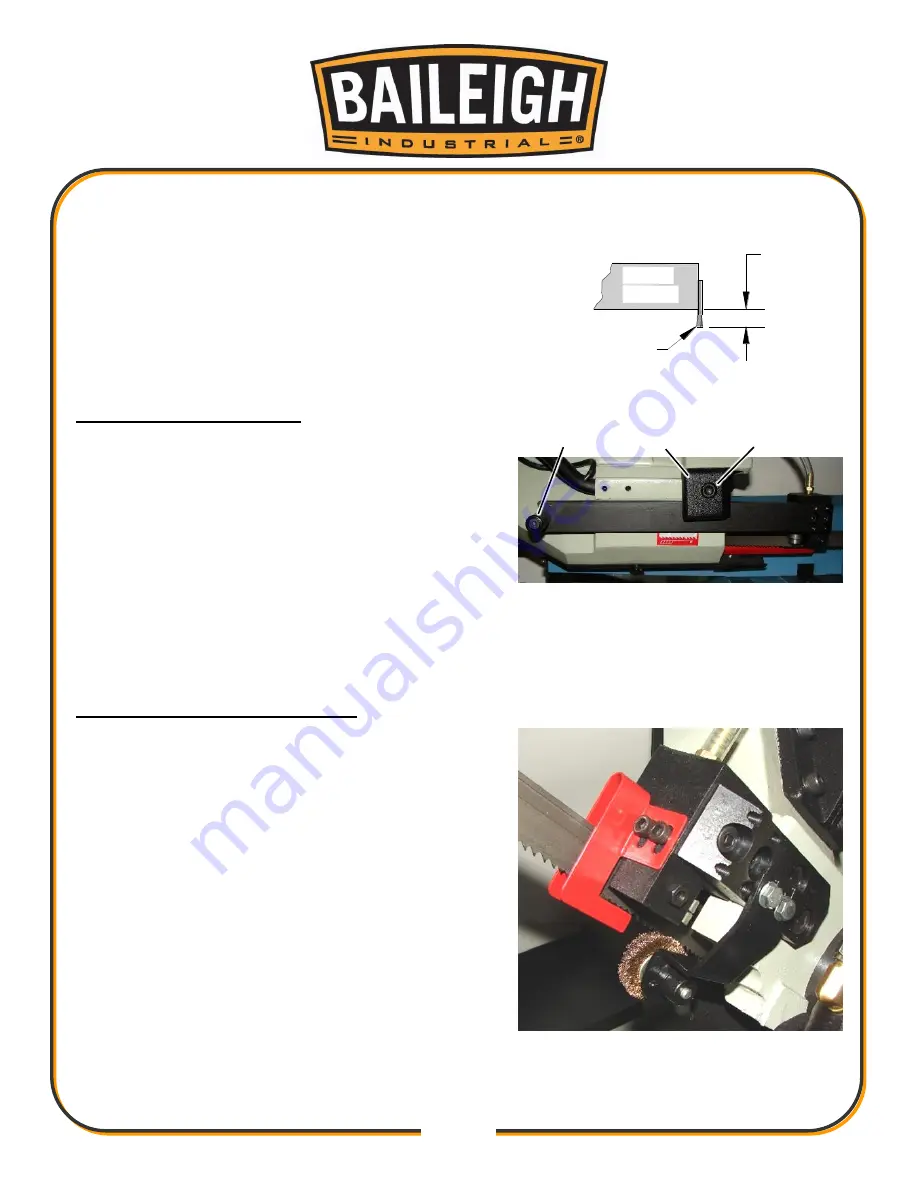
0.19"

approx.

Blade
Wheel

Blade
Teeth

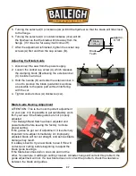
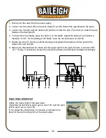
5.  Turning the setscrew (C) clockwise (cw) will tilt the flywheel so that the blade will ride closer 

to the flange. 

6.  Turning the setscrew (C) counterclockwise (ccw) will tilt 

the flywheel so that the blade will ride away from the 
flange. (If it rides too far away it will come off).  

7.  After the adjustment is finished, tighten the socket cap 

screws (A) first and then the cap screws (B). 


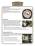
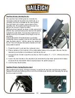
Adjusting the Blade Guide 

1.  Disconnect the saw from the power supply. 

2.  Loosen the socket cap screw (A) which releases 

the clamping block (B) allowing the extension bar 
(C) to slide in and out. 

3.  Hold the handle (D) and slide the extension bar in 

or out to position the blade guide block as close 
as possible to the piece part without interfering 
with the cut. 

4.  Tighten socket screw (A) clockwise (cw). 


Blade Guide Bearing Adjustment 

ATTENTION: This is the most important adjustment 
on your saw. It is impossible to get satisfactory work 
from your saw if the blade guides are not properly 
adjusted. 
Your Baileigh Band Saw has been adjusted and 
power tested before leaving the factory to insure 
proper setting. 
If the guides do get out of adjustment, it is extremely 
important to re-adjust immediately. An improperly 
adjusted blade will not cut straight, and serious blade 
damage may result. 
It is always best to try a new blade to see if this will 
correct poor cutting before beginning to adjust the 
blade guide bearings. 
If the blade becomes dull on one side and not the 
other, for example, it will begin cutting crooked. A blade change will correct this problem; the 
guide adjustment will not. If a new blade does not correct the problem, check the clearance 
between the blade and guides. 

Summary of Contents for BS-350SA

Page 1: ...NDUSTRIAL HOLDINGS LLC IS PROHIBITED Baileigh Industrial Holdings LLC Inc does not assume and hereby disclaims any liability for any damage or loss caused by an omission or error in this Operator s Ma...

Page 2: ...22 ELECTRICAL 25 BEFORE EACH USE 27 Whenever Saw is Running 27 Breaking in a Band Saw Blade 28 Metal Chip Indicators 28 Blade Terminology 29 Width of Blade 29 Length of Blade 29 Blade structure 30 Bl...

Page 3: ...essing and Cleaning the Coolant System 44 Coolant System Maintenance 44 Oils for Lubricating Coolant 44 Gearbox Maintenance 45 Storing Machine for Extended Period of Time 45 ELECTRICAL SCHEMATIC 46 HY...

Page 4: ...n notice to Seller of any suspected defect in the Goods prior to the expiration of the warranty period The original end user must also obtain a RGA from Seller prior to returning any Goods to Seller f...

Page 5: ...emedies provided under this Agreement or at law or equity Attorney s Fees In the event legal action is necessary to recover monies due from Buyer or to enforce any provision of this Agreement Buyer sh...

Page 6: ...Description of the functional parts of the machine Capacity charts Setup and start up instructions Machine operation Scheduled maintenance Parts lists GENERAL NOTES After receiving your equipment remo...

Page 7: ...zardous situation which if not avoided will result in death or serious injury WARNING Indicates a hazardous situation which if not avoided could result in death or serious injury CAUTION Indicates a h...

Page 8: ...s to protect against objectionable or uncomfortable loud noises HYDRAULIC HOSE FAILURE Exercise CAUTION around hydraulic hoses in case of a hose or fitting failure DUST HAZARD Wear appropriate dust ma...

Page 9: ...TON In the event of incorrect operation or dangerous conditions the machine can be stopped immediately by pressing the E STOP button Twist the emergency stop button clockwise cw to reset Note Resettin...

Page 10: ...igh does not recommend or endorse making any modifications or alterations to a Baileigh machine Modifications or alterations to a machine may pose a substantial risk of injury to the operator or other...

Page 11: ...art that appears damaged Check for alignment and binding of moving parts that may affect proper machine operation 15 Observe work area conditions DO NOT use machines or power tools in damp or wet loca...

Page 12: ...pm Coolant Pump 1 16hp 40W 220V 60Hz 1Ph 42A Shipping Weight 1080lbs 490kgs Shipping Dimensions L x W x H 73 x 30 x 67 1854 x 762 x 1702mm TECHNICAL SUPPORT Our technical support department can be rea...

Page 13: ...age painted surfaces Follow manufacturer s label instructions when using any type of cleaning product After cleaning wipe unpainted metal surfaces with a light coating of quality oil or grease for pro...

Page 14: ...ne Remove the securing bolts that attach the machine to the pallet Approaching the machine from the side lift the machine on the frame taking care that there are no cables or pipes in the area of the...

Page 15: ...adequate working area around the machine for safety Have the work area well illuminated with proper lighting Keep the floor free of oil and make sure it is not slippery Remove scrap and waste material...

Page 16: ...ling The hydraulic oil is the primary medium for transmitting pressure and also must lubricate the running parts of the pump After installation of the machine and before machine startup bring the oil...

Page 17: ...14 14 OVERALL DIMENSIONS...

Page 18: ...15 15 GETTING TO KNOW YOUR MACHINE I H G F E D C B A T P O Q S M N U L R V J K T...

Page 19: ...r is used to provide the down and up force to lower and lift saw bow K Saw Bow Limit Switches The limit switches which control the down travel and the up travel of the saw bow The down limit switch ha...

Page 20: ...ration Select Switch Choose between hand or foot pedal operation AB Main Disconnect Switch Turns power ON to the saw Can be locked out in the OFF position for Safety or Security AC Indicator Lights Va...

Page 21: ...r The blade motor may be at fault overloaded or shorted 6 Broken Blade Warning Indicator Light The saw blade is broken loose or off of the drive wheels 7 Control Panel Emergency Button Indicator Light...

Page 22: ...ver R to the left and by retracting stop pin AF Rotate the saw head to the desired angle as shown on the angle indicator Q Lock the saw head by pushing the lock lever R to the right as shown Note Pin...

Page 23: ...eft The vise C may now be moved to the left position figure 5 or the right position figure 6 by pushing it with one hand on the vise and the other hand on the track handle L Once in position move the...

Page 24: ...ydraulic unit must be running Footpad Switch Using the side of your foot push aside the plastic clip that blocks the footpad of footswitch T Be careful not to damage the clip by using excessive force...

Page 25: ...justment of the saw Also included are two handles and a test slug of material that was cut on this saw First remove the 2 socket capscrews from the control box support post A Set and position the supp...

Page 26: ...moving through the vise Attaching the support roller to the left side of the base Remove the 2 hex bolts lock washers and flat washers from the base Place the support roller U up to the machine base...

Page 27: ...asily read by the operator Tighten setscrew until rod is tight Positioning the E Stop footswitch pedestal Locate the pedestal at the front of the saw near the base operating controls as shown The oper...

Page 28: ...s as indicated on the machine All line connections should make good contact Running on low voltage will damage the motor In the event of a malfunction or breakdown grounding provides a path of least r...

Page 29: ...he machine is properly grounded Repair or replace damaged or worn cord immediately Power cord connection 1 Turn the main disconnect switch on the control panel to the OFF position 2 Unwrap the power c...

Page 30: ...the cut off piece can move sideways after it is cut off Otherwise it could get wedged against the blade and thrown violently Never turn the saw ON before clearing everything except the work piece ben...

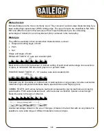
Page 31: ...s approximately 300cm of the material should be cut for breaking in If large work piece dimensions are to be cut we recommend a breaking in period of about 15 minutes After breaking in you may slowly...

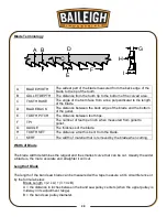
Page 32: ...easured from gullet to gullet G GAUGE The thickness of the blade H TOOTH SET The distance a tooth is bent from the blade I KERF The width of material that is removed by the blade when cutting Width of...

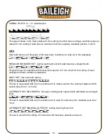
Page 33: ...for transversal or inclined cutting of solid small and average cross sections or pipes in laminated mild steel and gray iron or general metal POSITIVE RAKE TOOTH 9 10 positive rake and constant pitch...

Page 34: ...l use for materials with dimensions superior to 5 mm Used for the cutting of steel castings and hard nonferrous materials WAVY SET Set in smooth waves This set is associated with very fine teeth and i...

Page 35: ...G A SAW BLADE A general purpose blade is furnished with this band saw To achieve a quality economical and efficient saw cut the following points must be taken into consideration Type of material being...

Page 36: ...33 33...

Page 37: ...below are some of the more common reasons for blade breakage Top blade guide assembly is set too high above the piece part The blade is tensioned incorrectly Piece part is fed into the blade too quic...

Page 38: ...it first between the guide blocks and then on the face of the flywheels NOTE the blade direction 6 Tension the blade making sure it seats properly on the flywheels 7 Position the blade cover A onto t...

Page 39: ...chine functions Replacement blades which duplicate the saws original blade specifications will not require adjustment of the limit switch If properly tensioned but the limit switch does not make conta...

Page 40: ...erfering with the cut 4 Tighten socket screw A clockwise cw Blade Guide Bearing Adjustment ATTENTION This is the most important adjustment on your saw It is impossible to get satisfactory work from yo...

Page 41: ...w A and B 5 Rotate the pins F and G until the bearings rest against the blade and then secure the dowels E and nuts D 6 Make sure that between the blade and the upper teeth of the pad K there is at le...

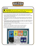
Page 42: ...blade about 1 25mm above the material to be cut This normally provides safe clearance to load and position material 1 Power the saw On and start the hydraulic motor 2 Place a sample of the material o...

Page 43: ...ust be activated depressed to start a cut cycle Either raise the bow to the switch or adjust the switch to the bow See Saw Bow Stroke Limiting Place the piece part in the vise and adjust the clamp fro...

Page 44: ...r the saw bow has return to its up position If the hand operation is selected and the footpad is used the hand operation indicator light will blink If the footpad operation is selected and the hand op...

Page 45: ...nd sliding devices Apply rust inhibitive lubricant to all non painted surfaces Wipe and grease the vise screw and sliding surfaces Inspect blade brush wheel and clean if needed Clean coolant pump stra...

Page 46: ...OT rely totally on the oil gauge as they can sometimes indicate an incorrect level reading Do a visual inspection with the oil fill cap removed as well A shortage of hydraulic oil will cause hydraulic...

Page 47: ...nd lift the cover off of the tank 4 Use a hex wrench to remove the drain plug from the tank to allow the coolant to drain out 5 Use a hydraulic vacuum to remove any chips and debris 6 Thoroughly clean...

Page 48: ...lug B will help oil to drain 4 After draining replace drain plug A 5 Return the saw bow to a horizontal position 6 Remove the fill plug B and add 0 32 quart of gear oil For reference use SHELL type ge...

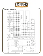
Page 49: ...46 46 ELECTRICAL SCHEMATIC...

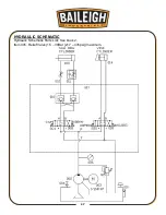
Page 50: ...47 47 HYDRAULIC SCHEMATIC Hydraulic Schematic Parts List See book 2 Item 005 Relief Valve 15 30Bar 217 435psi maximum...

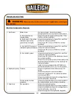
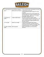
Page 51: ...se FU3 6A on the distributor board for normal condition Check the connection points of the safety limit switches at their locations on the machine for normal condition refer to the wire diagram No WT...

Page 52: ...ck the related components for an over load or short circuit Check the switches and see if each one is correctly positioned 7 Speed control switch VR1 Indicator light blinking Check the speed control s...

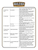
Page 53: ...switch wires No 61 71 12 Emergency button Indicator light blinking See if the emergency switch is stuck Check the wire connections Wires No 61 66 in the emergency switch on saw body wires No 61 65 fo...

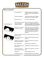
Page 54: ...braking device Change speed and or type of blade See section on choosing a blade Choose a suitable blade Check for clogging of coolant drain holes on the blade guide blocks and that flow is plentiful...

Page 55: ...nt Use slow speeds when making first few cuts Generously spray the cutting area with lubricating coolant Turn teeth to correct direction The Blade needs to be turned inside out Use a superior quality...

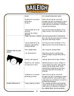
Page 56: ...or incorrect lubricating coolant Check distance between pads Extremely close guiding may cause cracks and breakage of the tooth Use extreme care when cleaning Position head as near as possible to mat...

Page 57: ...relation to the vise and adjust vertically Adjust the vise head stop screws if the cut angles are off Check and vertically re adjust the blade guide blocks reset proper side guide play Decrease advan...

Page 58: ...55 55 NOTES...

Page 59: ...56 56 NOTES...

Page 60: ...TOWOC WI 54220 PHONE 920 684 4990 FAX 920 684 3944 www baileigh com BAILEIGH INDUSTRIAL HOLDINGS LTD UNIT D SWIFT POINT SWIFT VALLEY INDUSTRIAL ESTATE RUGBY WEST MIDLANDS CV21 1QH UNITED KINGDOM PHONE...

Reviews: