49
49
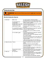
valve for normal condition (Bow up wire No. 9
and 21; bow down wire No. 9 and 17.)
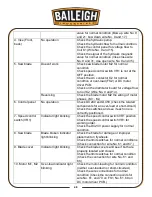
4. Vise (Front,
back)
No operation
Check the hydraulic pump.
Check the hydraulic flow for normal condition.
Check the control panel for voltage flow to
Coil K1 (Wire No. 9 and 15).
Check the signal of the hydraulic magnetic
valve for normal condition (Vise close wire
No. 9 and 31; vise open wire No. 9 and 35.)
5. Saw blade
Doesn’t work
Check saw blade motor M2 for normal
condition
Check speed control switch VR1 is not at the
OFF position.
Check the AC contactor K2 for normal
condition or over-load (FS2) or DC motor
driver PCB.
Check on the distributor board for voltage flow
to Coil K2 (Wire No. 9 and 14).
Reversing
Check the blade motor M2 the wiring of motor
phases. (M+ , M-)
6. Control panel
No operation
Check DC24V and DC5V (check the related
components for an over-load or short-circuit.)
Check the switches and see if each one is
correctly positioned.
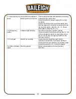
7. Speed control
switch (VR1)
Indicator light blinking
Check the speed control switch VR1 position.
Check the speed control switch VR1 for
working order.
Check the DC24V power supply for normal
condition.
8. Saw blade
Blade broken indicator
light blinking
Check the blade for damage or improper
placement on flywheels.
Check the limit switches for normal conditions
(Check connection for wire No. 61 and 67.)
9. Blade cover
Indicator light blinking
Check the blade covers and see if both are
properly located and closed.
Check the limit switches for normal condition
(Check the connection for wire No. 61 and
68.)
10. Motor M1, M2 Over-load indicator light
blinking
Check the motor-loading for normal condition
(neither over-loaded nor short-circuited.)
Check the wire connections for normal
condition (Check the connection points for
wire No. 61, and 70 on FS1, No. 61, 69 on
DC motor driver PCB.)
Summary of Contents for BS-350SA
Page 17: ...14 14 OVERALL DIMENSIONS...
Page 18: ...15 15 GETTING TO KNOW YOUR MACHINE I H G F E D C B A T P O Q S M N U L R V J K T...
Page 36: ...33 33...
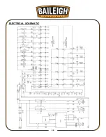
Page 49: ...46 46 ELECTRICAL SCHEMATIC...
Page 58: ...55 55 NOTES...
Page 59: ...56 56 NOTES...

