background image


32 

32 


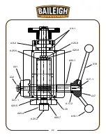
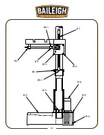
A6-2

A6-3

A6-1

A6-4

A8-1

A8-2

A5

A5-1

A33-1

A19-1

A33

Summary of Contents for DP-1000VS

Page 1: ...L HOLDINGS LLC IS PROHIBITED Baileigh Industrial Holdings LLC Inc does not assume and hereby disclaims any liability for any damage or loss caused by an omission or error in this Operator s Manual resulting from accident negligence or other occurrence Rev 08 2020 Baileigh Industrial Holdings LLC P O Box 531 Manitowoc WI 54221 0531 Phone 920 684 4990 Fax 920 684 3944 sales baileigh com ...

Page 2: ... Height 23 OPERATION 24 Drilling 24 Tapping 25 Removing Tooling from Spindle 25 DRILLING RECOMMENDATIONS 26 LUBRICATION AND MAINTENANCE 28 Greasing the Machine 28 Spindle Return Spring Adjustment 29 Accessing and Cleaning the Coolant System 29 Oils for Lubricating Coolant 29 Timing Belt Replacement 30 Storing Machine for Extended Period of Time 30 DRILL HEAD PARTS DIAGRAM 31 Drill Head Parts List ...

Page 3: ...CHUCK GUARD PART DIAGRAM 45 Chuck Guard Parts List 46 ELECTRICAL SCHEMATIC 47 ELECTRICAL ENCLOSURE COMPONENTS 48 Electrical Component Parts List 49 TROUBLESHOOTING 50 TROUBLESHOOTING THE INVERTER 52 ...

Page 4: ...en notice to Seller of any suspected defect in the Goods prior to the expiration of the warranty period The original end user must also obtain a RGA from Seller prior to returning any Goods to Seller for warranty service under this paragraph Seller will not accept any responsibility for Goods returned without a RGA The original end user shall be responsible for all costs and expenses associated wi...

Page 5: ...remedies provided under this Agreement or at law or equity Attorney s Fees In the event legal action is necessary to recover monies due from Buyer or to enforce any provision of this Agreement Buyer shall be liable to Seller for all costs and expenses associated therewith including Seller s actual attorney fees and costs Governing Law Venue This Agreement shall be construed and governed under the ...

Page 6: ... Description of the functional parts of the machine Capacity charts Setup and start up instructions Machine operation Scheduled maintenance Parts lists GENERAL NOTES After receiving your equipment remove the protective container Do a complete visual inspection and if damage is noted photograph it for insurance claims and contact your carrier at once requesting inspection Also contact Baileigh Indu...

Page 7: ...azardous situation which if not avoided will result in death or serious injury WARNING Indicates a hazardous situation which if not avoided could result in death or serious injury CAUTION Indicates a hazardous situation which if not avoided could result in minor or moderate injury NOTICE Indicates a situation which if not avoided could result in property damage IMPORTANT PLEASE READ THIS OPERATORS...

Page 8: ...oud noises BEWARE OF PIERCING POINTS AND CUTTING HAZARD NEVER place hands fingers or any part of your body on or near rotating tooling This tooling can be extremely dangerous if you do not follow proper safety procedures Keep hand at least 6 inches 150mm from the tooling while operating DUST HAZARD Wear appropriate dust mask Dust created while using machinery can cause cancer birth defects and lon...

Page 9: ...OP BUTTON In the event of incorrect operation or dangerous conditions the machine can be stopped immediately by pressing the E STOP button Twist the emergency stop button clockwise cw to reset Note Resetting the E Stop will not start the machine CALIFORNIA PROPOSITION 65 WARNING Cancer and Reproductive Harm www P65Warnings ca gov ...

Page 10: ...eigh does not recommend or endorse making any modifications or alterations to a Baileigh machine Modifications or alterations to a machine may pose a substantial risk of injury to the operator or others and may do substantial damage to the machine Any modifications or alterations to a Baileigh machine will invalidate the machine s warranty PLEASE ENJOY YOUR BAILEIGH MACHINE PLEASE ENJOY IT SAFELY ...

Page 11: ...achine 13 Stay alert Watch what you are doing and use common sense DO NOT operate any tool or machine when you are tired 14 Check for damaged parts Before using any tool or machine carefully check any part that appears damaged Check for alignment and binding of moving parts that may affect proper machine operation 15 Observe work area conditions DO NOT use machines or power tools in damp or wet lo...

Page 12: ... comes to a complete stop Hold the piece part firmly against the table DO NOT attempt to drill a piece part that does not have a flat surface against the table or that is not secured by a vise Prevent the piece part from rotating by clamping it to the table or by securing it against the drill press column Never start the machine before clearing the table of all objects tools scrap pieces etc Prope...

Page 13: ...on 1 25 31 75mm Drilling Capacity Mild Steel 1 25 4mm Tapping Capacity Cast Iron 75 19 05mm Tapping Capacity Mild Steel 625 15 875mm Spindle To Table Maximum Distance 23 8 604mm Spindle To Base Maximum Distance 45 3 1150mm Spindle To Column Maximum Distance 10 4375 265 1mm Coolant Capacity 2 Gal 7 5L Spindle Spindle Taper MT 3 Spindle Speed Variable 150 3000rpm Spindle Travel 5 3 134mm Rotation Fw...

Page 14: ...hipping Weight 574lbs 260kg TECHNICAL SUPPORT Our technical support department can be reached at 920 684 4990 and asking for the support desk for purchased machines Tech Support handles questions on machine setup schematics warranty issues and individual parts needs other than die sets and blades For specific application needs or future machine purchases contact the Sales Department at sales baile...

Page 15: ...mage painted surfaces Follow manufacturer s label instructions when using any type of cleaning product After cleaning wipe unpainted metal surfaces with a light coating of quality oil or grease for protection Important This waxy coating is NOT a lubricant and will cause the machine to stick and lose performance as the coating continues to dry WARNING SUFFOCATION HAZARD Immediately discard any plas...

Page 16: ...loor Level the machine so that all the supporting feet are taking the weight of the machine and no rocking is taking place Follow these guidelines when lifting crane or hoist Always lift and carry the machine with the lifting straps around the head of the machine Take proper precautions for handling and lifting Remove the coolant valve bracket from the head to avoid damaging it DO NOT let the lift...

Page 17: ...well illuminated with proper lighting Keep the floor free of oil and make sure it is not slippery Remove scrap and waste materials regularly and make sure the work area is free from obstructing objects If long lengths of material are to be fed into the machine make sure that they will not extend into any aisles LEVELING The machine should be sited on a level concrete floor Provisions for securing ...

Page 18: ...rical codes if installing new circuits and or outlets Anchoring the Machine Once positioned anchor the machine to the floor as shown in the diagram Use bolts and expansion plugs or sunken tie rods that connect through and are sized for the holes in the base of the stand This machine requires a solid floor such as concrete at a minimum of 4 102mm thick 6 153mm minimum is preferred 31 7 87mm 50 12 7...

Page 19: ...16 16 OVERALL DIMENSIONS ...

Page 20: ...17 17 GETTING TO KNOW YOUR MACHINE Q F P J B C A G H I L M E F D N O K R ...

Page 21: ...nd tapping L Depth Stop Knob Moves the depth stop up and down M Safety Guard Adjustable guard with limit switch shut off N Depth Indicator Used for setting the drill or tap depth O Halogen Work Light Provides additional light directly toward the work area P Control Panel Houses the operating controls Q Work Table Adjustable table with T slots R Main Power Disconnect Turns main power on to the oper...

Page 22: ...f spindle rotation AE Drilling Tapping Selector Switch Selects the mode of operation drilling or tapping AF Start Button Starts the spindle motor A 10 sec wait is required before a machine restart or the machine will not start AG Stop Button Stops the spindle motor AH Emergency Stop Button Stops all machine functions Turn the switch clockwise cw to reset the switch DIGITAL INDICATOR RPM 0 l 150 30...

Page 23: ...ow the use of 1 2 or M14 bolts Below the work table are three crankshafts The two crankshafts F control the up down motion of the table Always unlock the table with crankshaft I before changing the height or rotating it Then lock the work table to secure in position The one handle works for all three crankshafts The Machine Base The machine base houses the coolant reservoir and supports the coolan...

Page 24: ... indicated on the machine All line connections should make good contact Running on low voltage will damage the motor In the event of a malfunction or breakdown grounding provides a path of least resistance for electric current to reduce the risk of electric shock This machine is equipped with an electric cord having an equipment grounding conductor and a grounding plug The plug must be plugged int...

Page 25: ...ted below LENGTH AMP RATING 25ft 50ft 100ft 1 12 16 16 14 13 16 14 12 12 17 20 12 12 10 21 30 10 10 No WIRE GAUGE An undersized cord decreases line voltage causing loss of power and overheating All cords should use a ground wire and plug pin Replace any damaged cords immediately Power cord connection 1 Turn the main disconnect switch on the control panel to the OFF position 2 Unwrap the power cord...

Page 26: ...w 3 Raise the gear rack G by turning either crankshaft F counterclockwise ccw 4 Unlock column bearing Y by loosening the two setscrews and sliding it up to the gear rack 5 Lock column bearing Y by tightening the two setscrews 6 After unlocking I the table can now be raised or lowered for normal operation CAUTION Failure to lock the collar can result in personal injury or damage to the machine F F ...

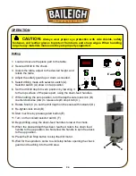
Page 27: ...he scale with indicator D 9 Re tighten lock knob B 10 Start machine by pressing start button E 11 Turn on the coolant selector switch F 12 Begin drilling using the down feed handles to lower the chuck 13 When the desired depth has been reached return the down feed handle to the up position Do Not allow the handle to spin free back to the up position 14 Press the Red Stop button to stop the drill m...

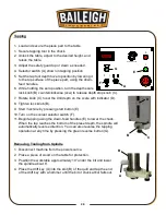
Page 28: ...ck knob B 9 Start machine by pressing start button E 10 Turn on the coolant selector switch F 11 Begin tapping using the down feed handles E to lower the chuck When the tap reaches the bottom of the preset depth the spindle will automatically reverse direction You can also reverse the tapping operation at any time by pressing the green reverse button G Removing Tooling from Spindle 1 Disconnect ma...

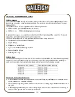
Page 29: ...drilling machine Desired quality of hole Difficulty of set up Drilling Feed The feed of a drill is governed by size of tool and the material drilled Because feed rate partially determines rate of production and also is a factor in tool life it should be chosen carefully for each job In general the most effective feeds will be found in the following ranges Diameter of Drill inches Feed per Revoluti...

Page 30: ...on 70 100 Soft Cast Iron 100 150 Malleable Iron 80 90 High Nickel Steel or Monel 40 50 High Tensile Bronze 70 150 Ordinary Brass and Bronze 200 300 Aluminum and its Alloys 200 300 Magnesium and its Alloys 250 400 Slate Marble and Stone 15 25 Plastics and similar materials Bakelite 100 150 Wood 300 400 Titanium Alloys 10 25 Titanium Alloy Sheet 50 60 Note In cases where carbon steel drills are appl...

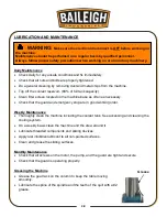
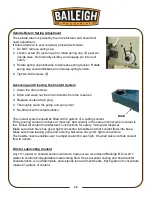
Page 31: ...weekly basis clean the machine and the area around it Lubricate threaded components and sliding devices Apply rust inhibitive lubricant to all non painted surfaces Clean and grease the sliding surfaces Monthly Maintenance Check that all screws on the motor the pump and the guard are tight and secure Check that the guard is operating properly Greasing the Machine Grease the gear rack on the column ...

Page 32: ...th coolant solution The coolant system should be filled with 2 gallons of a cutting coolant Fill by pouring coolant into base of machine Add coolant in the same manner when coolant is low Follow all coolant manufacturer s instructions for safety mixing and disposal Make sure drain hose has good tight connection into table and that coolant flows into base Make sure hose leaving pump and entering ba...

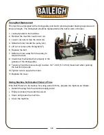
Page 33: ...Replace the belt 7 Slide the motor away from the pulley to tension the belt 8 Check that the belt teeth sit properly in the grooves of the timing pulley 9 Tension should be loose enough to allow 197 394 5 10 mm movement when pushing the belt from the side 10 Tighten nuts to secure the motor 11 Replace the cover Storing Machine for Extended Period of Time If the Drill Press is to be inactive for a ...

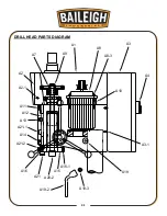
Page 34: ...31 31 DRILL HEAD PARTS DIAGRAM A4 A3 A8 3 A8 A10 A3 1 A1 A9 A7 A2 A2 1 A11 A12 A13 A21 1 A14 A15 A16 A21 2 A21 A20 2 A15 1 A19 2 A19 3 A19 ...

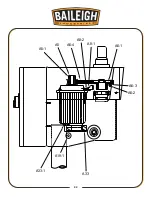
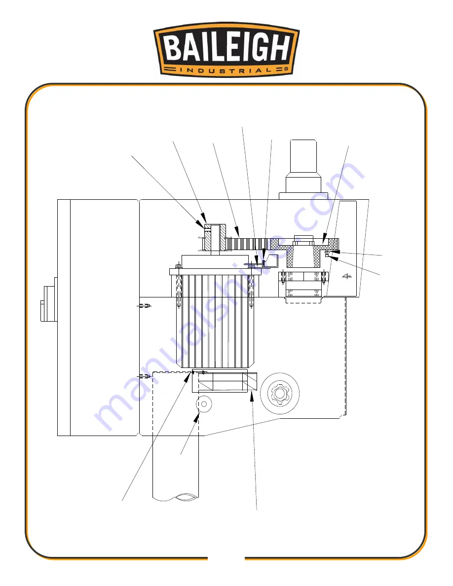
Page 35: ...32 32 A6 2 A6 3 A6 1 A6 4 A8 1 A8 2 A5 A5 1 A33 1 A19 1 A33 ...

Page 36: ...33 33 A20 7 A30 A17 2 A17 1 A17 A18 A18 1 A30 1 A20 9 A20 8 A9 1 A9 2 A20 6 A31 A32 A31 1 A20 5 A20 4 A20 2 ...

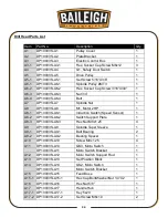
Page 37: ...HP 1 A8 1 DP1000VS A8 1 Induction Switch Speed Sensor 1 A8 2 DP1000VS A8 2 Switch Support Plate 1 A8 3 DP1000VS A8 3 Hex Nut M8x1 25 4 A9 DP1000VS A9 Spindle Taper Sleeve 1 A9 1 DP1000VS A9 1 Ball Bearing 2 A9 2 DP1000VS A9 2 Bearing Spacer 1 A10 DP1000VS A10 Screw M8x1 25 4 A11 DP1000VS A14 QS3 Micro Switch 1 DP1000VS A11 Micro Switch Bracket 1 A12 DP1000VS A12 Micro Switch Support Rod 1 A13 DP10...

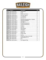
Page 38: ...3 1 A20 4 DP1000VS A20 4 Quill MT3 1 A20 5 DP1000VS A20 5 Taper Roller Bearing 1 A20 6 DP1000VS A20 6 Taper Roller Bearing 1 A20 7 DP1000VS A20 7 Oil Seal 1 A20 8 DP1000VS A20 8 Jam Nut 2 A20 9 DP1000VS A20 9 Star Washer 1 A21 DP1000VS A21 Scale Rod 1 A21 1 DP1000VS A21 1 Limit Block 1 A21 2 DP1000VS A21 2 Screw 1 4 1 A30 DP1000VS A30 Pinion Shaft 1 A31 DP1000VS A31 Spring 1 A31 1 DP1000VS A31 1 C...

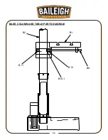
Page 39: ...36 36 BASE COLUMN AND TABLE PARTS DIAGRAM B1 B2 B11 B10 B9 B10 1 ...

Page 40: ...37 37 B3 B4 B6 1 B6 B5 1 B5 2 B8 B8 1 B12 B13 B16 B15 B14 ...

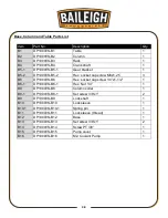
Page 41: ...1 25 3 B6 DP1000VS B6 Hex socket cap screw 1 4 x1 1 2 1 B6 1 DP1000VS B6 1 Hex Nut 1 4 1 B8 DP1000VS B8 Column collar 1 B8 1 DP1000VS B8 1 Set screw 3 8 x1 2 B9 DP1000VS B9 Lock shaft 1 B10 DP1000VS B10 Lock sleeve 1 B10 1 DP1000VS B10 1 Spring pin 1 B11 DP1000VS B11 Lock sleeve thread 1 B12 DP1000VS B12 Base 1 B13 DP1000VS B13 Set screw 3 8 x1 2 B14 DP1000VS B14 Screw PT 3 8 1 B15 DP1000VS B15 Pu...

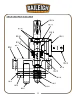
Page 42: ...39 39 TABLE GEAR PARTS DIAGRAM B5 7 B5 8 B5 9 B5 10 B5 18 B5 11 B5 12 B5 13 B5 14 B5 15 B5 16 B5 17 B5 2 B5 1 B5 3 B5 4 B5 5 B5 6 ...

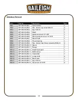
Page 43: ...m gear set screw 1 4 x3 8 1 B5 7 DP1000VS B5 7 Worm shaft 1 B5 8 DP1000VS B5 8 Thrust bearing 1 B5 9 DP1000VS B5 9 Hex Socket Cap Screw w washer M6x20 2 B5 10 DP1000VS B5 10 Sleeve 1 B5 11 DP1000VS B5 11 Flange 1 B5 12 DP1000VS B5 12 Small bevel gear 1 B5 13 DP1000VS B5 13 Ball bearing 1 B5 14 DP1000VS B5 14 Crankshaft 1 B5 15 DP1000VS B5 15 C Clip S 25 2 B5 16 DP1000VS B5 16 Bevel gear 1 B5 17 DP...

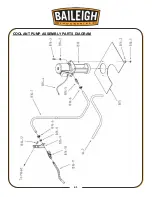
Page 44: ...41 41 COOLANT PUMP ASSEMBLY PARTS DIAGRAM ...

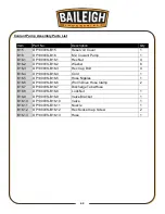
Page 45: ...r 8 B16 3 DP1000VS B16 3 Hex Cap Bolt 4 B16 4 DP1000VS B16 4 Cord 1 B16 5 DP1000VS B16 5 Hose Nipples 1 B16 6 DP1000VS B16 6 Worm Drive Hose Clamp 2 B16 7 DP1000VS B16 7 Discharge Tube Hose B16 8 DP1000VS B16 8 Lock Nut 1 B16 9 DP1000VS B16 9 Valve Bracket 1 B16 10 DP1000VS B16 10 Valve 1 B16 11 DP1000VS B16 11 Nozzle 1 B16 12 DP1000VS B16 12 Hex Socket Cap Screw 2 B16 13 DP1000VS B16 13 Hose 1 ...

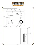
Page 46: ...43 43 CONTROL PANEL PARTS DIAGRAM ...

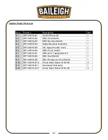
Page 47: ...D4 DP1000VS D4 Digital Readout Assembly 1 D5 DP1000VS D5 VR Speed Control Knob 1 D6 DP1000VS D6 SB6 Pump Switch 1 D7 DP1000VS D7 SB4 Drill Tapping Switch 1 D8 DP1000VS D8 SB3 Start Switch 1 D9 DP1000VS D9 SB1 Emergency Stop Switch 1 D10 DP1000VS D10 Cross Head Screw 3 16 x3 8 4 D11 DP1000VS D11 Graduated Dial Label 1 D12 DP1000VS D12 Cross Head Screw 3 16 x3 8 4 ...

Page 48: ...45 45 CHUCK GUARD PART DIAGRAM ...

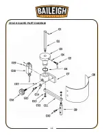
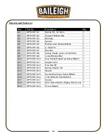
Page 49: ... Bracket 1 G8 DP15VSF G8 Safety Shield Lexan 410x210mm 1 G9 DP15VSF G9 Lower Bracket Bar 1 G10 DP15VSF G10 Hex Socket Head Cap Screw M8x12 1 G11 DP15VSF G11 Support Arm 1 G12 DP15VSF G12 Hex Nut 3 8 1 G13 DP15VSF G13 Spring Washer 3 8 1 G14 DP15VSF G14 Spacer 1 G15 DP15VSF G15 Socket Head Cap Screw M8x20 1 G16 DP15VSF G16 Lock Bolt with Knob M8x18 1 G17 DP15VSF G17 Spacer 1 G18 DP15VSF G18 QS1 Mic...

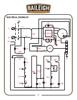
Page 50: ...CTRICAL SCHEMATIC SB1 24V L1 PE FU2 220V QS1 SB2 3 1 FU3 FU1 KM1 L2 L1 KM1 KM2 KM1 PL SB5 V2 U2 M2 KR M1 B2 B1 W V U VR 200W 70 PE 4 8 SB6 KR KM2 KR 7 6 QS3 4 R S T VFD B SB3 12 0 0 5 31 1 1 Q1 L2 1 SB4 0 3 3 4 ...

Page 51: ...48 48 ELECTRICAL ENCLOSURE COMPONENTS ...

Page 52: ... 1ph 50 60Hz 0 23A 24V 2 1A VFD M Variable Speed AC Motor Driver 230VAC 7A 1 5KW BR Braking Resistors 2hp 230V 200W 70Ω VR Adjust Speed Switch 0 05Ω Max SB2 Push Button Stop 600V PL 24V 1a 250V 10A 1b SB3 Push Button Start 600V PL 24V 1a 250V 10A 1b SB1 Emergency Stop 250V 10A SB4 Drill Tapping Switch 250V 3A SB5 Push Button Reverse 600V 250V 10A 1a SB6 Pump Switch Coolant 600V 250V 10A 1a XB Term...

Page 53: ...N locked position Make sure limit switch actuator is in the center detent position Replace limit switch Wait 10 sec for the Delta motor controller to reset Push the start button Excessive Vibration Improper belt tension Uneven belt wear hard spots Motor or spindle pulley out of balance Bad motor Adjust belt tension Replace belt Balance or replace problem pulley Replace motor Motor Stalls Over feed...

Page 54: ...No drill spot Cutting lips on drill off center Quill loose in head Bearing play Center punch or center drill work piece Regrind drill Tighten quill Check bearings and reseat or replace if necessary Excessive Drill Runout or Wobble Bent drill bit or tool Bearing play Drill not seated properly in chuck Replace drill bit or tool Do Not attempt to straighten Replace or reseat bearings Loosen reseat an...

Page 55: ...detects that the output current exceeds the normal value Check if motor voltage matches that of the voltage inverter Check connection between the motor and the voltage inverter Check if the motor is overloaded O U The voltage inverter of the motor is detected with a D C high voltage lateral pressure value that exceeds the acceptable range Check if the circuit input voltage matches that of the volt...

Page 56: ...or error U phase error W phase error Replace the Inverter BAILEIGH INDUSTRIAL HOLDINGS LLC 1625 DUFEK DRIVE MANITOWOC WI 54220 PHONE 920 684 4990 FAX 920 684 3944 www baileigh com BAILEIGH INDUSTRIAL HOLDINGS LTD UNIT D SWIFT POINT SWIFT VALLEY INDUSTRIAL ESTATE RUGBY WEST MIDLANDS CV21 1QH UNITED KINGDOM PHONE 44 0 24 7661 9267 FAX 44 0 24 7661 9276 WWW BAILEIGH CO UK ...

Reviews: