background image


28 

28 

ADDITIONAL OPERATION 

 
The following directions will give the inexperienced operator a beginning point for common lathe 
operations. Practice on scrap material before attempting serious work. 


Lathe Tools 

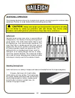
Standard  wood  turning  tools  come  in  several  different 
configurations.  The majority of turnings will require the 
gouge tool (A). This round nosed hollow chisel is used 
for roughing cuts, cove cuts and other operations. The 
skew chisel (B) is  a  double-ground  flat  chisel,  with  an 
angled  end.  This  tool  is  used  for  smoothing cylinders, 
for cutting shoulders, beads, vee grooves, etc. The 
parting tool (C) is a double-ground  chisel,  used  for 
cutting-off,  or  for  making  straight  incisions  or  sizing 
cuts to any required diameter. The round nose scraper 
(D) is used for mostly hollowing work, while the square-
end scraper is mainly used for the outside of bowls. 


Selecting Turning Tools 

 
Lathe tools come in a variety of shapes and sizes and usually fall into five major categories. 
 
• 

Gouges

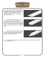
—Main use is for rough cutting, 

detail cutting, and cove profiles. The rough gouge 
is a hollow, double-ground tool with a round nose, 
and the detail gouge is a hollow, double-ground 
tool with either a round or pointed nose. An 
example of a gouge is shown. 


CAUTION: 

Always wear proper personal protection equipment, including 

but  not  limited  to,  safety  eye  protection  with  side  shields,  face  shield,  safety 
footwear, and leather gloves to protect from, chips, dust, burrs, and slivers. 

Summary of Contents for WL-1218VS

Page 1: ... INDUSTRIAL INC IS PROHIBITED Baileigh Industrial Inc does not assume and hereby disclaims any liability for any damage or loss caused by an omission or error in this Operator s Manual resulting from accident negligence or other occurrence Rev 08 2015 Baileigh Industrial Inc P O Box 531 Manitowoc WI 54221 0531 Phone 920 684 4990 Fax 920 684 3944 sales baileigh com ...

Page 2: ...19 BASIC ADJUSTMENT 20 Change Spindle Speed 20 Electronic Variable Speed Control 21 Tool Rest 22 Face Plate 22 Index Pin 23 Headstock Spur Center 24 Tailstock Live Center 24 Tailstock Quill 25 Tailstock 25 OPERATION 26 Mounting The Workpiece 27 ADDITIONAL OPERATION 28 Lathe Tools 28 Selecting Turning Tools 28 SPINDLE TURNING 30 Centering the Work 30 Tool Rest Position 32 Roughing a Cylinder 32 Pos...

Page 3: ...LATHE PARTS DIAGRAM 39 Parts List 40 TROUBLESHOOTING 43 Motor Electrical 43 Wood Lathe Operation 44 ...

Page 4: ...ce to Seller of any suspected defect in the Goods prior to the expiration of the warranty period The original end user must also obtain a RGA from Seller prior to returning any Goods to Seller for warranty service under this paragraph Seller will not accept any responsibility for Goods returned without a RGA The original end user shall be responsible for all costs and expenses associated with retu...

Page 5: ...further remedies provided under this Agreement or at law or equity Attorney s Fees In the event legal action is necessary to recover monies due from Buyer or to enforce any provision of this Agreement Buyer shall be liable to Seller for all costs and expenses associated therewith including Seller s actual attorneys fees and costs Governing Law Venue This Agreement shall be construed and governed u...

Page 6: ...ption of the functional parts of the machine Capacity charts Set up and start up instructions Machine operation Scheduled maintenance Parts lists GENERAL NOTES After receiving your equipment remove the protective container Do a complete visual inspection and if damage is noted photograph it for insurance claims and contact your carrier at once requesting inspection Also contact Baileigh Industrial...

Page 7: ...ies a hazard or unsafe practice that will result in severe Injury or Death Safety signs with signal word DANGER or WARNING are typically near specific hazards General precautions are listed on CAUTION safety signs CAUTION also calls attention to safety messages in this manual IMPORTANT PLEASE READ THIS OPERATORS MANUAL CAREFULLY It contains important safety information instructions and necessary o...

Page 8: ...ect against objectionable or uncomfortable loud noises DUST HAZARD Wear appropriate dust mask Dust created while using machinery can cause cancer birth defects and long term respiratory damage Be aware of the dust hazards associated with all types of materials ENTANGLEMENT HAZARD ROTATING SPINDLE Contain long hair DO NOT wear jewelry or loose fitting clothing ROTATING TOOL HAZARD Keep hands and bo...

Page 9: ...OUT PROCEDURES Power Switch with Lock Out In the event of incorrect operation or dangerous conditions the machine can be stopped immediately by pressing the Power Switch paddle downward Remove the yellow lock key to prevent the machine from starting Note Resetting the Power Switch WILL start the machine ...

Page 10: ...s well as the specific hazards 2 Only trained and qualified personnel should operate this machine 3 Make Sure lathe is located on a flat stable surface 4 Make sure guards are in place and in proper working order before operating machinery 5 Face Eye Protection Always wear a face shield to protect from flying debris while the machine is running 6 Stopping the Lathe DO NOT try and stop the lathe by ...

Page 11: ... not overreach Maintain proper footing and balance at all times DO NOT reach over or across a running machine 20 Stay alert Watch what you are doing and use common sense DO NOT operate any tool or machine when you are tired 21 Maintenance and Adjustments Before starting any inspection adjustment or maintenance procedure MAKE SURE the lathe is OFF has come to a complete stop and the electrical has ...

Page 12: ...the lathe chisels on the downward spinning side of the piece part ONLY 34 Maintain machine in top condition Keep clean for best and safest performance Follow instructions for lubricating and changing accessories 35 Reduce the risk of unintentional starting Make sure switch is in OFF position before plugging in power cord 36 Never leave machine running unattended TURN POWER OFF Don t leave machine ...

Page 13: ...eight 106 lbs 48kgs TECHNICAL SUPPORT Our technical support department can be reached at 920 684 4990 and asking for the support desk for purchased machines Tech Support handles questions on machine setup schematics warranty issues and individual parts needs other than die sets and blades For specific application needs or future machine purchases contact the Sales Department at sales baileigh com ...

Page 14: ...ed surfaces Follow manufacturer s label instructions when using any type of cleaning product After cleaning wipe unpainted metal surfaces with a light coating of quality oil or grease for protection Important This waxy coating is NOT a lubricant and will cause the machine to stick and lose performance as the coating continues to dry WARNING SUFFOCATION HAZARD Immediately discard any plastic bags a...

Page 15: ...e machine as well behind it in the places of material input and output LEVELING The machine should be sited on a level concrete floor Provisions for securing it should be in position prior to placing the machine The accuracy of any machine depends on the precise placement of it to the mounting surface FLOOR This tool distributes a large amount of weight over a small area Make certain that the floo...

Page 16: ...hrough the holes in the base The strongest mounting option is a Through Mount where holes are drilled all the way through the workbench and hex bolts washers and hex nuts are used to secure the machine to the workbench Another option for mounting is a Direct Mount where the machine is simply secured to the workbench with a lag screw Whichever method you choose it is crucial that the workbench is p...

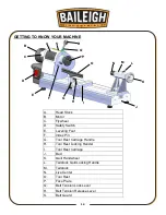
Page 17: ...F Index Pin G Tool Rest Carriage Handle H Tool Rest Locking Handel I Tool Rest Carriage J Bed K Quill Handwheel L Tailstock Quill Locking Handle M Tailstock N Live Center O Tool Rest P Face Plate Q Belt Tension Lock Lever R Belt Tension Release Lever S Belt Guard A B C D E F G H I J K L M N O P R Q S ...

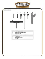
Page 18: ...15 15 Tools and Tooling A Face Plate Wrench B Belt Tension Release Lever C Knock Out Bar D Headstock Spur Center E Live Center F Hex Wrench 3mm G Tool Rest A B C D E F G ...

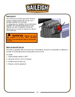
Page 19: ...y in a safe inconspicuous place in your workshop Motor Overload Protector The lathe is equipped with a manual reset circuit breaker If the tool is overloaded or stalled too long the circuit breaker will trip causing the tool to shut off To restart 1 Set the Safety switch to OFF 2 Allow the motor to cool 3 5 minutes 3 Press the reset button A 4 Resume normal operations WARNING Always be sure the sw...

Page 20: ...on release lever as shown 2 Install the tool rest on the tool rest carriage WARNING For your own safety DO NOT connect the machine to the power source until the machine is completely assembled and you read and understand the entire instruction manual A ...

Page 21: ...e will damage the motor In the event of a malfunction or breakdown grounding provides a path of least resistance for electric current to reduce the risk of electric shock This tool is equipped with an electric cord having an equipment grounding conductor and a grounding plug The plug must be plugged into a matching outlet that is properly installed and grounded in accordance with all local codes a...

Page 22: ...elow LENGTH AMP RATING 25ft 50ft 100ft 0 6 16 16 16 7 10 16 16 14 11 12 16 16 14 13 16 14 12 12 17 20 12 12 10 21 30 10 10 No WIRE GAUGE An undersized cord decreases line voltage causing loss of power and overheating All cords should use a ground wire and plug pin Replace any damaged cords immediately Power cord connection 1 Verify the safety paddle switch is in the OFF position 2 Unwrap the power...

Page 23: ...d experience and when in doubt always start at a slower speed increasing when you are sure that it is safe to do so Note Use the chart as a base guideline for selecting the appropriate spindle speed Speed Recommendations Diameter of work Roughing Finishing Low High Low High Under 2 in 51 mm 950 1500 1900 3000 2 in to 4 in 51 mm to 107 mm 500 750 1500 2300 4 in to 6 in 107 mm to 152 mm 500 750 1500...

Page 24: ...nd pulleys lift up the belt guard 3 Release the belt tension locking lever B then release the tension on the belt by pulling the belt tension release lever C 4 Set the belt by hand to the required pulley position High Medium Low Be certain that the belt is tracking straight between the pullies 5 Push the belt tension release lever forward to re tension the belt and lock the belt tension locking le...

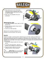
Page 25: ...djustment of the tool rest clamping device become necessary turn OFF the machine reach under the bed and adjust the clamping nut Note The locking handle is adjustable Simple pull up on the handle rotate it on the pin and then release Make sure the lock handle seats itself properly upon the pin Face Plate IMPORTANT To reduce the risk of injury when using the included 3 76 mm faceplate A do not moun...

Page 26: ...d for workpiece layout and other auxiliary operations that require equal distances around the workpiece circumference such as clock faces or inlays By inserting the indexing pin into one of the three outer indexes of the lathe spindle housing and engaging one of the twelve inner indexes in the spindle the workpiece can be positioned one of 36 equal points 1 Turn off and unplug the lathe from the p...

Page 27: ...from falling Tailstock Live Center The tailstock has an MT 2 taper hole into which the live center fits 1 Turn off and unplug the lathe from the power source 2 Make sure the shank of the live center A and the tailstock hole are clean and free of debris 3 Using hand force only fit the live center firmly in the spindle hole 4 To remove the live center A from the tailstock quill fully retract the qui...

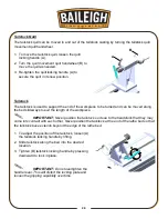
Page 28: ...ed along the bed slideways to suit the length of the workpiece IMPORTANT Never position the tailstock so close to the headstock that they may come into contact with each other Never position the tailstock at the end of the lathe bed so that the tailstock base extends beyond the edge of the lathe bed 1 To adjust the position of the tailstock loosen A the tailstock locking handle by lifting 2 Slide ...

Page 29: ...pply water or other coolants to lathe when it is spinning Do not turn materials other than wood on this lathe This lathe was designed for wood turning only Be sure any chuck keys or wrenches are out of the chuck before operating the lathe Be sure to only use accessories equipped with locking set screws for turning the lathe in reverse Also do not switch lathe turning directions until the workpiece...

Page 30: ...urned Mounting a Spindle Workpiece The workpiece is fixed between the spur and live centers 1 Mount the workpiece by moving the tailstock to a position about 1 1 1 2 25mm 38mm from the end of the workpiece and locking it in this position 2 Advance the live center by turning the tailstock quill handwheel until the center cup makes contact with the workpiece 3 Do not support the workpiece on the cen...

Page 31: ...el used for cutting off or for making straight incisions or sizing cuts to any required diameter The round nose scraper D is used for mostly hollowing work while the square end scraper is mainly used for the outside of bowls Selecting Turning Tools Lathe tools come in a variety of shapes and sizes and usually fall into five major categories Gouges Main use is for rough cutting detail cutting and c...

Page 32: ...limited such as hollowing operations This is a flat double ground tool that comes in a variety of profiles Round Nose Spear Point Square Nose etc to match many different contours An example of a round nose scraper is shown Parting Tools Used for sizing and cutting off work This is a flat tool with a sharp pointed nose that may be single or double ground An example of a parting tool is shown Specia...

Page 33: ...or small sized workpieces under 2 in diameter Make sure the turning tool is against the tool rest the ENTIRE time that the turning tool is in contact with the workpiece Learn the correct techniques for each tool you will use If you are unsure read books or magazines about lathe techniques and seek training from experienced users Turn the lathe OFF immediately if the workpiece vibrates excessively ...

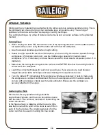
Page 34: ...nes and drilling a small hole at the intersection After driving the center hold the center and the work together and fit both immediately to headstock spindle If you are not using a ball bearing center the end of work at tailstock center should be oiled Place the lubricant on the wood either before or after it is put on the lathe Many turners use beeswax tallow or a wax and oil mixture as a lubric...

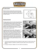
Page 35: ...tock and merge with the previous cut Toward the end of the live center roll the gouge in the opposite direction to carry the final cut off the live center end of the work The roughing cut should not be carried out with one continuous movement because this would tear long slivers from the corners of the work Neither should the cut be started directly at the end of the stock for the same reason The ...

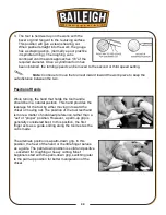
Page 36: ...ands While turning the hand that holds the tool handle should be in a natural position This hand provides the leverage for the tool by either moving in toward the chisel or moving out The position of the tool rest hand is more a matter of individual preference rather than a set or proper position However a palm up grip is generally considered best In this position the first finger acts as a guide ...

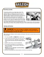
Page 37: ... on this pivot point Because of this keep the skew bevel perfectly flat Sanding and Finishing After turning the workpiece can be sanded and finished in the same manner before removing it from the lathe 1 Turn the lathe OFF and REMOVE the Lockout Key 2 Loosen the tool rest release lever and move the tool rest as far away from the workpiece as possible to increase personal safety and gain adequate w...

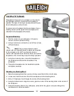
Page 38: ... the workpiece Do NOT use drywall screws or screws with tapered heads because these can split the faceplate or the screws may snap off during operation 3 Using the centering lines center the faceplate on the workpiece and screw the faceplate to the workpiece 4 Thread the faceplate onto the headstock spindle and tighten securely Mounting to a Backing Block 1 Make the backing block from a piece of s...

Page 39: ...n order Clean and oil the lathe beds so that the headstock tailstock and tool support base will slide easily Clean any rust spots that may develop on the bed with a commercial rust remover Use compressed air to blow out the interior of the headstock in order to keep chips and sawdust from accumulating on the belts and pulleys Clean out the Morse tapers on both the headstock and tailstock Commercia...

Page 40: ...ush life expectancy is affected by motor loading Heavy motor loading will result in reduced brush life Check brushes after every 40 50 hours of operation 1 Unplug or disconnect lathe from power source and lock out power 2 One at a time remove the brush cap and brush and spring assembly 3 Measure the brush length When the brushes are worn down to 1 4 6mm replace them Note When checking brushes be s...

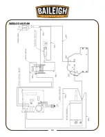
Page 41: ...38 38 WIRING DIAGRAM ...

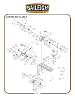
Page 42: ...39 39 LATHE PARTS DIAGRAM ...

Page 43: ...ing 6004 1 13 011001 105 Spring Pin 3 14 2 14 000302 201 Pan HD Screw M4 0 7P 6 4 16 051354 000 Headstock 1 17 250589 000 Window 1 19 171959 000 Belt Guard 1 20 380764 902 Index Pin 1 21 000104 111 Cap Screw M8 1 25P 35 1 23 014320 000 Poly V Belt 140J 5R 1 24 000203 102 Set Screw M6 1 0P 8 1 25 090167 000 Spindle Pulley 1 26 030201 001 Ball Bearing 6005 1 27 012003 007 Key 5 5 20 1 28 360837 000 ...

Page 44: ...C 1 33 14 471002 006 Motor Cord SJT16AWG 1C 3 33 16 006501 100 Tooth Washer 4 3 8 5 2 33 17 000302 101 Pan HD Screw M4 0 7P 6 2 34 000303 107 Pan HD Screw M5 0 8P 20 4 35 006302 100 Spring Washer 5 1 9 3 3 36 380670 902 Locking Handle 1 37 010003 000 Retaining Ring STW 12 2 38 160058 000 Bushing 1 39 050813 000 Tool Rest Carriage 1 40 070037 902 Tool Rest 1 41 006001 009 Flat Washer 5 2 10 1 0t 4 ...

Page 45: ...50812 000 Tailstock 1 58 921455 001 Locking Handle 1 59 380409 902 Locking Lever 1 60 360369 901 Tailstock Screw 1 61 003201 101 Set Screw 1 4 20NC 1 4 1 62 240053 906 Handwheel 1 63 380857 000 Handle 1 64 380408 905 Connect Rod 1 67 172318 904 Face Plate Wrench 1 68 380559 905 Knock Out Bar 1 ...

Page 46: ...ey replace switch 4 Replace faulty ON button or ON OFF switch 5 Check for broken wires or disconnected corroded connections and repair replace as necessary 6 Replace brushes 7 Test repair replace Machine stalls or is Overloaded 1 Too much tool pressure 2 Plug receptacle is at fault 3 Motor bearings are at fault 4 Motor brushes are worn 5 Motor overheated 6 Motor is at fault 1 Reduce tool pressure ...

Page 47: ...es when speed is changed 1 Belt cover loose 1 If necessary install a soft vibration dampening material between the belt cover and the headstock casting Motor is running but spindle is not turning 1 Belt is loose broken or has come off pulleys 1 Inspect belt and tighten reinstall or replace if damaged Excessive vibration 1 Workpiece mounted incorrectly 2 Workpiece warped out of round or is flawed 3...

Page 48: ...ace the chisel tool you are using Bad surface finish 1 Wrong spindle speed 2 Dull chisel or wrong chisel being used for the operation 1 Use trial and error to find a better spindle speed 2 Sharpen chisel or try a different chisel Tailstock moves 1 Tailstock mounting bolt loose 2 Too much clamping pressure applied by tailstock 3 Bed surface is oily or greasy 1 Tighten 2 Apply less clamping pressure...

Page 49: ...46 46 NOTES ...

Page 50: ...47 47 NOTES ...

Page 51: ...48 48 NOTES ...

Page 52: ...49 49 BAILEIGH INDUSTRIAL INC 1625 DUFEK DRIVE MANITOWOC WI 54220 PHONE 920 684 4990 FAX 920 684 3944 www baileigh com ...

Reviews: