12
12
OPERATION
The MH-19 Reciprocating Hammer is a multi-stroke reciprocating machine, capable of many
different metal forming operations. In the next few steps, we will explain each mode of operation
as well as setting the tooling
Power Hammer Mode
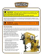
In power hammer mode, the upper slide ram is connected to the crank toggle mechanism via a
multi stack leaf spring. As the crank turns, speed and momentum load the spring which in turn
“throws” the upper slide ram down with spring force and gravity. The amount of throw and force
are controlled by speed and/or stroke.
The speed is controlled through a
variable foot control and a limiting
potentiometer on the upper control box.
The foot control fully depressed will max
out at whatever the limiting potentiometer
is set to.
1. To set the machine to power hammer
mode the control box must be turned
in the “off” position.
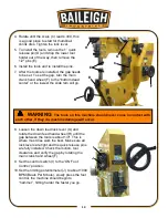
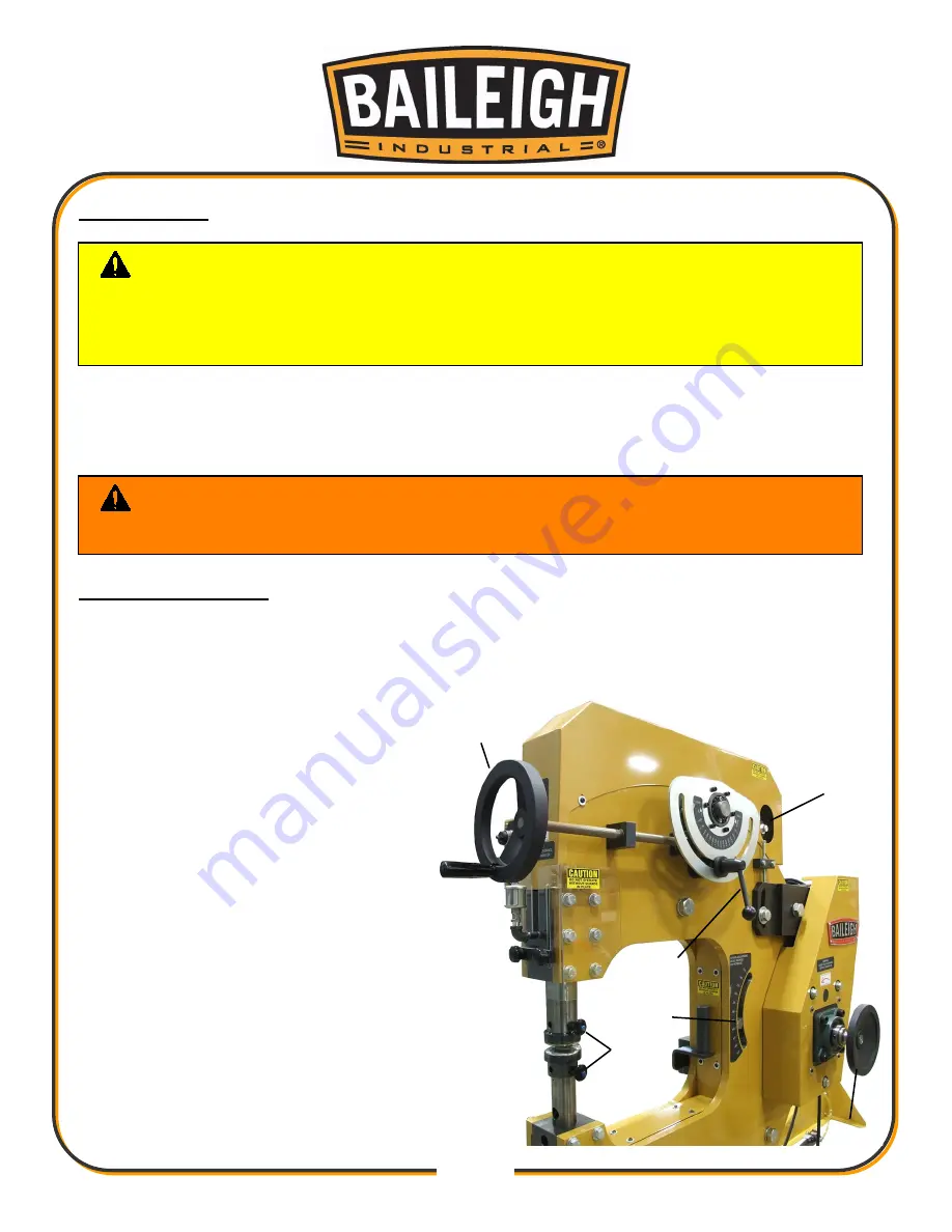
2. Remove the shear bolt (A) and
bushings in the upper rear lever
connection point. Store the bolt and
spacer bushings in a safe place.
Removing the bolt will separate the
leaf spring from rigid mode and the
spring will be free to move.
3. Next, the stroke can be set. Insert the
hand wheel (B) onto the hex shaft.
CAUTION:
Always wear proper hearing and eye protection with side
shields, safety footwear, and leather gloves to protect from burrs and sharp edges.
Keep hands and fingers clear of the hammer dies.
When handling large heavy sheets make sure they are properly supported.
WARNING:
HEARING PROTECTION MUST BE WORN AT ALL TIMES
WHEN OPERATING THIS MACHINE.
A
H
G
C
F
E
Summary of Contents for B8935
Page 1: ...OPERATOR S MANUAL POWER HAMMER MODEL MH 19 B8935 2015 Baileigh Industrial Inc Rev 04 2015...
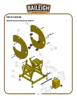
Page 19: ...17 17 PARTS DIAGRAM Stand Frame Assembly Parts Diagram...
Page 20: ...18 18 Slide Block Assembly Parts Diagram...
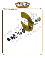
Page 21: ...19 19 Pulley Assembly Parts Diagram...
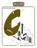
Page 22: ...20 20 Crankshaft Assembly Parts Diagram...
Page 23: ...21 21 Clevis Shaft Assembly Parts Diagram...
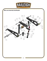
Page 24: ...22 22 Bell Crank Assembly Parts Diagram...
Page 25: ...23 23 Main Lever Assembly Parts Diagram...
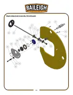
Page 26: ...24 24 Height Adjustment Assembly Parts Diagram...
Page 27: ...25 25 Left Hand Frame Assembly Parts Diagram...
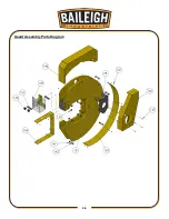
Page 28: ...26 26 Guard Assembly Parts Diagram...
Page 35: ...33 33 NOTES...
Page 36: ...34 34...


