13
13
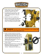
4. Rotate until the scale (C) reads .400, this
is a good place to start for thumbnail
shrink dies. Tighten the lock lever.
5. To install the tools, remove the 1” quick
release pin (D) and drop the lower tool
holder out of the way, then remove the
1/2" pins (E).
6. Install the tools and re install the pins.
7. After the tools are installed, the gap needs
to be set. To set the gap, turn the main
crank hand wheel (F) to the “bottom dead
center” or the lowest the slide ram will go.
8. Loosen the down feed lock lever (G) and
rotate the down feed hand wheel (H) until the
gap between the tools is about 1/4". This is
where most dies work the best. Make sure all
lock levers are tight and the quick release pins
are fully installed. Check the motion, tool
clearance and verify the gap by rotating the
main crank hand wheel (F).
9. Set the control switch (I) to the “ON Foot
Control” position.
10. Set the limiting potentiometer (J) to about 1000
BPM (Beats Per Minute), slowly press the foot
control, the machine should begin to
“hammer”, hitting harder the faster you go.
WARNING:
The tools on this machine should never come in contact with
each other, if they do, machine damage will occur.
C
B
E
D
F
G
H
J
I
Summary of Contents for B8935
Page 1: ...OPERATOR S MANUAL POWER HAMMER MODEL MH 19 B8935 2015 Baileigh Industrial Inc Rev 04 2015...
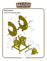
Page 19: ...17 17 PARTS DIAGRAM Stand Frame Assembly Parts Diagram...
Page 20: ...18 18 Slide Block Assembly Parts Diagram...
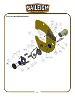
Page 21: ...19 19 Pulley Assembly Parts Diagram...
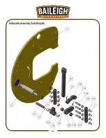
Page 22: ...20 20 Crankshaft Assembly Parts Diagram...
Page 23: ...21 21 Clevis Shaft Assembly Parts Diagram...
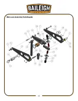
Page 24: ...22 22 Bell Crank Assembly Parts Diagram...
Page 25: ...23 23 Main Lever Assembly Parts Diagram...
Page 26: ...24 24 Height Adjustment Assembly Parts Diagram...
Page 27: ...25 25 Left Hand Frame Assembly Parts Diagram...
Page 28: ...26 26 Guard Assembly Parts Diagram...
Page 35: ...33 33 NOTES...
Page 36: ...34 34...


