16
16
•
Check with a qualified electrician or service personnel if the grounding instructions are not
completely understood, or if in doubt as to whether the tool is properly grounded.
•
Repair or replace damaged or worn cord immediately.
Extension Cord Safety
Extension cord should be in good condition and meet the minimum wire gauge requirements
listed below:
LENGTH
AMP RATING
25ft
50ft
100ft
0-6
16
16
16
7-10
16
16
14
11-12
16
16
14
13-16
14
12
12
17-20
12
12
10
21-30
10
10
No
WIRE GAUGE
An undersized cord decreases line voltage, causing loss of power and overheating. All cords
should use a ground wire and plug pin. Replace any damaged cords immediately.
Power cord connection:
1. Turn the main disconnect switch on the control panel to the OFF position.
2. Unwrap the power cord and route the cord away from the machine toward the power supply.
Route the power cord so that it will NOT become entangled in the machine in any way.
Route the cord to the power supply is a way that does NOT create a trip hazard.
3. Connect the power cord to the power supply and check that the power cord has not been
damaged during installation.
4. When the hammer and dies area is clear of any obstruction. The main disconnect may be
turn ON to test the operation. Turn the main disconnect to OFF when the machine is not in
operation.
IMPORTANT:
DO NOT allow the cord to become and entanglement or trip hazard.
DO NOT allow the cord to have material dropped or resting on the cord causing it to be pinched
or cut. DO NOT allow the cord to be positioned in a way that will allow it to be stepped on or
rolled over.
Summary of Contents for BP-3142NC
Page 3: ......
Page 16: ...13 13 GETTING TO KNOW YOUR MACHINE A B C D E G H I F J K L M N O ...
Page 24: ...21 21 Punch and Die Specifications ...
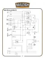
Page 28: ...25 25 ELECTRICAL SCHEMATIC ...
Page 29: ...26 26 PARTS DIAGRAMS Base Assembly Parts Diagram ...
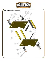
Page 30: ...27 27 Main Frame Assembly Parts Diagram ...
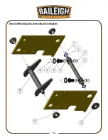
Page 31: ...28 28 Trunnion Bending Arm Assembly Parts Diagram ...
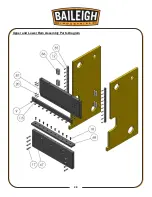
Page 32: ...29 29 Upper and Lower Ram Assembly Parts Diagram ...
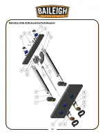
Page 33: ...30 30 Back Stop Slide Shaft Assembly Parts Diagram ...
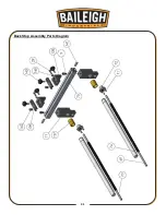
Page 34: ...31 31 Back Stop Assembly Parts Diagram ...
Page 35: ...32 32 Chain Tensioner Assembly Parts Diagram ...
Page 36: ...33 33 Cylinder Assembly Parts Diagram ...
Page 37: ...34 34 Travel Limit Assembly Parts Diagram ...
Page 38: ...35 35 Linkage Assembly Parts Diagram ...
Page 39: ...36 36 Cross Plate Assembly Parts Diagram ...
Page 40: ...37 37 Tooling Assembly Parts Diagram ...
Page 46: ...43 43 NOTES ...
Page 47: ...44 44 NOTES ...


