18
18
•
The counter reads incrementally in inches of ram travel. These numbers can be documented
for every different size of material for future reference of degrees.
•
Cut some sample material to perform some test bends.
•
Rotate the ram position (A) CCW and you will watch the ram slowly extend into the lower die
opening, these end positions will be relative to bend angles.
•
Retract the ram with the up foot penal until the top ram is about 1/4" above the material
being bent.
•
At this point rotate the retract position hand wheel (B) CW until the two indicator arrows (C)
are aligned with each other. This sets the ram retract position.
•
Press the
“Down”
foot pedal again until it reaches its end position. Switch the machine to
“AUTO”
mode. The top ram will automatically return to the retract position that was just set.
•
Adjust the back stop (D) as required.
•
Insert a piece of test material and activate the
“down”
foot pedal and hold until the ram
reaches it fully extended position. When the pressure gauge displays 2500psi, release the
foot pedal.
•
Check the bend angle of the sample and adjust the ram position accordingly to achieve the
desired bend angle. It is always best to make the ram position adjustments in the
“down”
direction. So if you need to go less degrees, rotate the ram position up, then back down and
gradually get to you final position in the down direction. This builds in accuracy and
consistency by removes any tolerance variation from the adjusting mechanism.
General Notes
•
Always bend in the center of the machine to avoid machine damage. This will evenly place
the load throughout the machine.
•
When bending heavier material hold the machine at the final position and let pressure build
up to the relief setting. This will ensure the ram fully reaches its end position making up for
the load of material.
•
Always make sure you have the correct tool with for the material being bent, having too tight
of an opening can damage the machine and tooling.
Summary of Contents for BP-3142NC
Page 3: ......
Page 16: ...13 13 GETTING TO KNOW YOUR MACHINE A B C D E G H I F J K L M N O ...
Page 24: ...21 21 Punch and Die Specifications ...
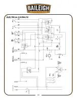
Page 28: ...25 25 ELECTRICAL SCHEMATIC ...
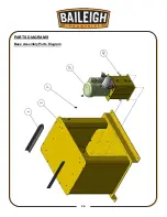
Page 29: ...26 26 PARTS DIAGRAMS Base Assembly Parts Diagram ...
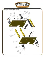
Page 30: ...27 27 Main Frame Assembly Parts Diagram ...
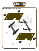
Page 31: ...28 28 Trunnion Bending Arm Assembly Parts Diagram ...
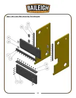
Page 32: ...29 29 Upper and Lower Ram Assembly Parts Diagram ...
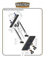
Page 33: ...30 30 Back Stop Slide Shaft Assembly Parts Diagram ...
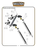
Page 34: ...31 31 Back Stop Assembly Parts Diagram ...
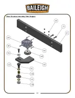
Page 35: ...32 32 Chain Tensioner Assembly Parts Diagram ...
Page 36: ...33 33 Cylinder Assembly Parts Diagram ...
Page 37: ...34 34 Travel Limit Assembly Parts Diagram ...
Page 38: ...35 35 Linkage Assembly Parts Diagram ...
Page 39: ...36 36 Cross Plate Assembly Parts Diagram ...
Page 40: ...37 37 Tooling Assembly Parts Diagram ...
Page 46: ...43 43 NOTES ...
Page 47: ...44 44 NOTES ...


