22
22
BENDING ALLOWANCE
In order to bend sheet metal accurately, you will need to consider the total length of each bend.
This is referred to as bend allowance. Subtract the bend allowance from the sum of the outside
dimensions of the piece part to obtain the actual overall length or width of the piece. Because of
differences in sheet metal hardness, and whether the bend is made with the grain or against it,
exact allowances must sometimes be made by trial and error. However bend allowances for
general use can be obtained from metal working books or from the Internet.
UNDERSTANDING SPRINGBACK
Springback, also known as elastic recovery, is the result of the metal wanting to return to its
original shape after undergoing compression and stretch. After the bending leaf is removed from
the metal and the load is released, the piece part relaxes, forcing the bent portion of the metal to
return slightly to its original shape. The key to obtaining the correct bend angle is to over bend
the metal a little and allow it to spring back to the desired angle. All metals exhibit a certain
amount of spring back.
MATERIAL SELECTION
When selecting materials keep these instructions in mind:
•
Material must be clean and dry. (without oil)
•
Material should have a smooth surface so it processes easily.
•
Dimensional properties of material must be consistent and not exceed the machine capacity
values.
•
Chemical structure of material must be consistent.
•
Buy certificated steel from the same vendor when possible.
CAUTION:
It must be determined by the customer that materials being
processed through the machine are NOT potentially hazardous to operator or
personnel working nearby.
Summary of Contents for BP-3142NC
Page 3: ......
Page 16: ...13 13 GETTING TO KNOW YOUR MACHINE A B C D E G H I F J K L M N O ...
Page 24: ...21 21 Punch and Die Specifications ...
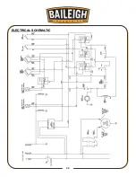
Page 28: ...25 25 ELECTRICAL SCHEMATIC ...
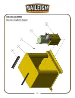
Page 29: ...26 26 PARTS DIAGRAMS Base Assembly Parts Diagram ...
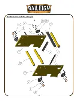
Page 30: ...27 27 Main Frame Assembly Parts Diagram ...
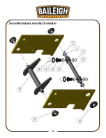
Page 31: ...28 28 Trunnion Bending Arm Assembly Parts Diagram ...
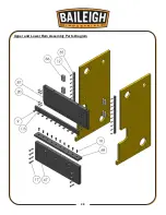
Page 32: ...29 29 Upper and Lower Ram Assembly Parts Diagram ...
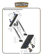
Page 33: ...30 30 Back Stop Slide Shaft Assembly Parts Diagram ...
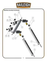
Page 34: ...31 31 Back Stop Assembly Parts Diagram ...
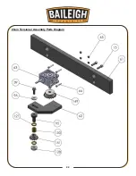
Page 35: ...32 32 Chain Tensioner Assembly Parts Diagram ...
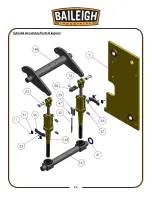
Page 36: ...33 33 Cylinder Assembly Parts Diagram ...
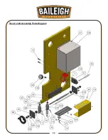
Page 37: ...34 34 Travel Limit Assembly Parts Diagram ...
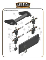
Page 38: ...35 35 Linkage Assembly Parts Diagram ...
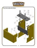
Page 39: ...36 36 Cross Plate Assembly Parts Diagram ...
Page 40: ...37 37 Tooling Assembly Parts Diagram ...
Page 46: ...43 43 NOTES ...
Page 47: ...44 44 NOTES ...


