24
24
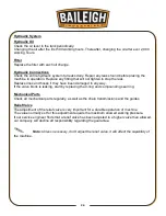
Hydraulic System
Hydraulic Oil
Check the oil level in the tank periodically.
Changing the oil after the first 500 working hours. Thereafter, changing the oil after ever 2,000
working hours.
Filter
Replace the filter with each oil change.
Hydraulic Connections
Check the entire hydraulic system for leaks daily. Repair any leaks found before placing the
machine in operation. Replace any fitting that will not tighten to stop the leak.
Replace lines and hoses if they have been damaged in any way.
If the valve block is leaking, start by replacing the 0-ring and compounding seal ring.
Mechanical Parts
Check all mechanical parts regularly, as well as the chain transmissions and the guides.
Relief Valve
The adjustment of the relief valve is very important for a durable operation of machine.
The value normally set for this adjustment equals the maximum allowed working pressure.
If our service engineer finds that a relief valve has been adjusted to a higher valve than allowed,
our company will decline all responsibility regarding the guarantee.
Note: Unless necessary, don't adjust the relief valve, it will affect the capability of
the machine.
Summary of Contents for BP-3142NC
Page 3: ......
Page 16: ...13 13 GETTING TO KNOW YOUR MACHINE A B C D E G H I F J K L M N O ...
Page 24: ...21 21 Punch and Die Specifications ...
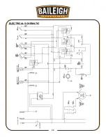
Page 28: ...25 25 ELECTRICAL SCHEMATIC ...
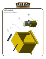
Page 29: ...26 26 PARTS DIAGRAMS Base Assembly Parts Diagram ...
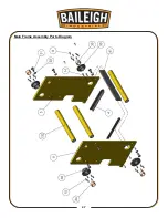
Page 30: ...27 27 Main Frame Assembly Parts Diagram ...
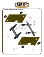
Page 31: ...28 28 Trunnion Bending Arm Assembly Parts Diagram ...
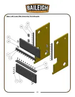
Page 32: ...29 29 Upper and Lower Ram Assembly Parts Diagram ...
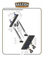
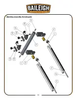
Page 33: ...30 30 Back Stop Slide Shaft Assembly Parts Diagram ...
Page 34: ...31 31 Back Stop Assembly Parts Diagram ...
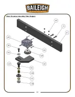
Page 35: ...32 32 Chain Tensioner Assembly Parts Diagram ...
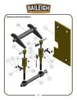
Page 36: ...33 33 Cylinder Assembly Parts Diagram ...
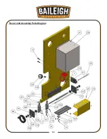
Page 37: ...34 34 Travel Limit Assembly Parts Diagram ...
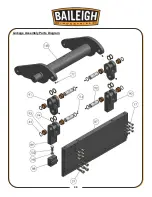
Page 38: ...35 35 Linkage Assembly Parts Diagram ...
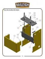
Page 39: ...36 36 Cross Plate Assembly Parts Diagram ...
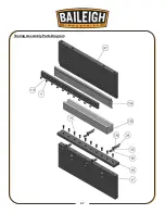
Page 40: ...37 37 Tooling Assembly Parts Diagram ...
Page 46: ...43 43 NOTES ...
Page 47: ...44 44 NOTES ...


