6
6
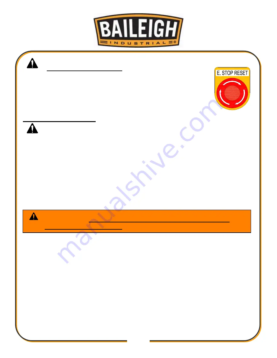
EMERGENCY STOP BUTTON
In the event of incorrect operation or dangerous conditions, the
machine can be stopped immediately by pressing the E-STOP
button. Twist the emergency stop button clockwise (cw) to reset.
Note: Resetting the E-Stop will not start the machine.
SAFETY PRECAUTIONS
Metal working can be dangerous if safe and proper operating procedures are not followed. As
with all machinery, there are certain hazards involved with the operation of the product. Using
the machine with respect and caution will considerably lessen the possibility of personal injury.
However, if normal safety precautions are overlooked or ignored, personal injury to the operator
may result.
Safety equipment such as guards, hold-downs, safety glasses, dust masks and hearing
protection can reduce your potential for injury. But even the best guard won’t make up for poor
judgment, carelessness or inattention. Always use common sense
and exercise caution in the
workshop. If a procedure feels dangerous, don’t try it.
REMEMBER:
Your personal safety is your responsibility.
1.
Only trained and qualified personnel can operate this machine.
2.
Make sure guards are in place and in proper working order before operating
machinery.
3.
Remove any adjusting tools.
Before operating the machine, make sure any adjusting tools
have been removed.
4.
Keep work area clean.
Cluttered areas invite injuries.
5.
Overloading machine.
By overloading the machine you may cause injury from flying parts.
DO NOT
exceed the specified machine capacities.
6.
Dressing material edges.
Before bending sheet metal, always chamfer and deburr all sharp
edges.
7.
Do not force tool.
Your machine will do a better and safer job if used as intended.
DO NOT
use inappropriate attachments in an attempt to exceed the machines rated capacity.
WARNING:
FAILURE TO FOLLOW THESE RULES MAY RESULT IN
SERIOUS PERSONAL INJURY
Summary of Contents for BP-3142NC
Page 3: ......
Page 16: ...13 13 GETTING TO KNOW YOUR MACHINE A B C D E G H I F J K L M N O ...
Page 24: ...21 21 Punch and Die Specifications ...
Page 28: ...25 25 ELECTRICAL SCHEMATIC ...
Page 29: ...26 26 PARTS DIAGRAMS Base Assembly Parts Diagram ...
Page 30: ...27 27 Main Frame Assembly Parts Diagram ...
Page 31: ...28 28 Trunnion Bending Arm Assembly Parts Diagram ...
Page 32: ...29 29 Upper and Lower Ram Assembly Parts Diagram ...
Page 33: ...30 30 Back Stop Slide Shaft Assembly Parts Diagram ...
Page 34: ...31 31 Back Stop Assembly Parts Diagram ...
Page 35: ...32 32 Chain Tensioner Assembly Parts Diagram ...
Page 36: ...33 33 Cylinder Assembly Parts Diagram ...
Page 37: ...34 34 Travel Limit Assembly Parts Diagram ...
Page 38: ...35 35 Linkage Assembly Parts Diagram ...
Page 39: ...36 36 Cross Plate Assembly Parts Diagram ...
Page 40: ...37 37 Tooling Assembly Parts Diagram ...
Page 46: ...43 43 NOTES ...
Page 47: ...44 44 NOTES ...


