11
11
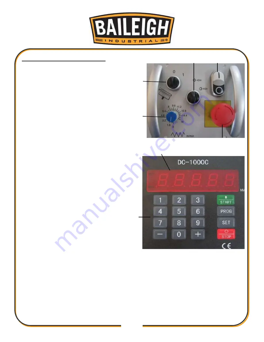
CONTROLS IDENTIFICATION
A.
Feed Motor On/Off Switch:
After the main
motor has been turned on for at least 5
seconds, this switch turns the feed motor
ON and OFF.
B.
Cutterhead Service Switch:
Turn to lock
the cutterhead for blade inspection and
change.
C.
Cutterhead Motor Switch:
Turns the
cutterhead ON/OFF
D.
Emergency Stop Button:
Immediately
turns the cutterhead/feed motor
OFF
and
stops all components of the planer.
E.
Feed Speed Adjustment Knob:
Adjusting the feeding speed after the
feeding motor is on.
F.
LED Readout:
Shows the current actual
table position value.
G.
Controller Keypad:
Used to enter table
presets elevations and digital commands.
A
B
C
D
E
F
G
Fig. 1
Fig. 2
Summary of Contents for IP-2511-HD
Page 39: ...36 36 ELECTRICAL SCHEMATIC...
Page 40: ...37 37...
Page 41: ...38 38...
Page 42: ...39 39...
Page 43: ...40 40 Electrical Cabinet Layout...
Page 44: ...41 41 CUTTERHEAD PARTS DIAGRAM...
Page 46: ...43 43 TABLE PARTS DIAGRAM...
Page 48: ...45 45 TABLE ROLLER PARTS DIAGRAM...
Page 50: ...47 47 INFEED PARTS DIAGRAM...
Page 52: ...49 49 STAND PARTS DIAGRAM...
Page 54: ...51 51 NOTES...
Page 55: ...52 52 NOTES...


