18
18
Test Headstock Cover Limit Switch:
1. Release the EMERGENCY STOP button by twisting
the knurled backside of the button clockwise until
the whole assembly pops out.
2. Start the planer by pushing the CUTTERHEAD
MOTOR switch.
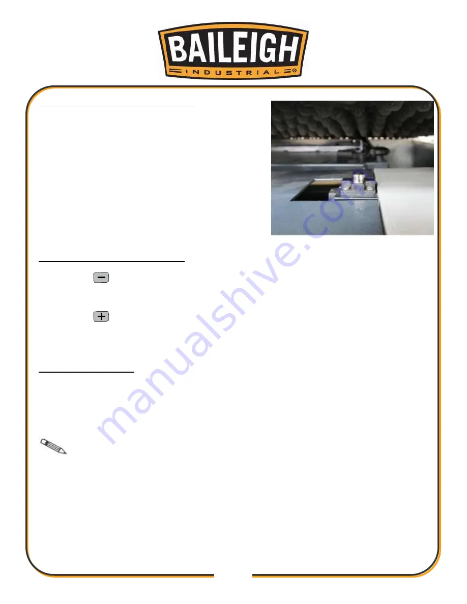
3. Slowly and with great care, lift the top cover up (Fig.
5) only about 1/2"
– 5/8” (13 - 16mm). When you do
this the machine should shut down immediately.
4. Lower the cover, and then secure it by twisting the
latches to the right.
Test Table Height Limit Switches:
1. Using the
button on digital control, carefully raise the table all the way up. The table
should stop by itself just before making contact with the headstock. The LED readout should
show the height is 6mm.
2. Using the
button, lower the table all the way down. The table should stop by itself at the
lowest limit for the table. LED readout should show the height is 300mm.
TIGHTEN V-BELTS
The final step in the set up process must be done after approximately 16 hours of operation.
During the first 16 hours, the V-belts will stretch and seat into the pulley grooves. After 16 hours,
the V- belts must be tensioned or they will slip and burn out.
Refer to
Replace/Adjust V-Belts
when you are ready to perform this important adjustment.
Note
: Pulleys and belts run very hot. This is a normal. Allow them to cool before
making adjustments.
Fig. 5
Summary of Contents for IP-2511-HD
Page 39: ...36 36 ELECTRICAL SCHEMATIC...
Page 40: ...37 37...
Page 41: ...38 38...
Page 42: ...39 39...
Page 43: ...40 40 Electrical Cabinet Layout...
Page 44: ...41 41 CUTTERHEAD PARTS DIAGRAM...
Page 46: ...43 43 TABLE PARTS DIAGRAM...
Page 48: ...45 45 TABLE ROLLER PARTS DIAGRAM...
Page 50: ...47 47 INFEED PARTS DIAGRAM...
Page 52: ...49 49 STAND PARTS DIAGRAM...
Page 54: ...51 51 NOTES...
Page 55: ...52 52 NOTES...


