24
24
V-BELT MAINTENANCE
V-belt removal and replacement is simply a matter of loosening the V-belts, rolling them off the
pulleys, replacing them with new belts, and then tensioning them.
This planer uses three V-belts to drive the cutterhead. Always replace the three cutterhead V-
belts with a matched set of three belts. Otherwise uneven belt tension may cause premature
belt failure.
Replace V-Belts:
1. UNPLUG OR DISCONNECT PLANER FROM POWER SOURCE AND LOCK OUT POWER.
2. Loosen the cap screws and remove the left hand
side lower access panel.
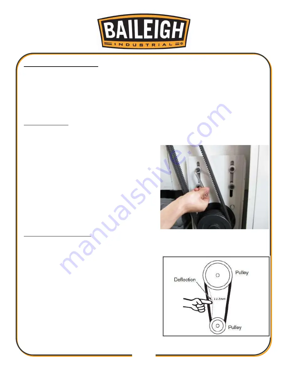
3. Loosen the four cap screws on the cutterhead
motor bracket shown in Figure 9.
4. With assistance, lift the motor up and slide all of
the V-belts off the pulleys.
5. Slide the new belts onto the pulleys and lower the
motor.
6. Adjust the tension of all three V-belts as
described in the next set of procedures.
Adjusting V-Belt Tension
1. UNPLUG OR DISCONNECT PLANER FROM POWER SOURCE AND LOCK OUT POWER.
2. Loosen the cap screws and remove the left hand
side lower access panel.
3. Loosen the four cap screws on the cutterhead
motor bracket shown in Figure 9.
4. With assistance, position the motor so that there
is about 1/4"
– 1/2" (6 12.5mm) deflection for each
of the cutterhead V-belts when moderate pressure
is applied midway between the pulleys. Fig. 10.
5. As you maintain the position of the motor, tighten
the bottom cap screws.
6. Tighten the top cap screws to hold the motor
firmly in place.
Fig. 9
Fig. 10
Summary of Contents for IP-2511-HD
Page 39: ...36 36 ELECTRICAL SCHEMATIC...
Page 40: ...37 37...
Page 41: ...38 38...
Page 42: ...39 39...
Page 43: ...40 40 Electrical Cabinet Layout...
Page 44: ...41 41 CUTTERHEAD PARTS DIAGRAM...
Page 46: ...43 43 TABLE PARTS DIAGRAM...
Page 48: ...45 45 TABLE ROLLER PARTS DIAGRAM...
Page 50: ...47 47 INFEED PARTS DIAGRAM...
Page 52: ...49 49 STAND PARTS DIAGRAM...
Page 54: ...51 51 NOTES...
Page 55: ...52 52 NOTES...


