35
35
SETTING/REPLACING KNIVES
Setting the knives correctly is crucial to the proper operation of the planer and is very important
in keeping the knives sharp. If one knife protrudes higher than the others, it will do the majority
of the work, and thus, dull much faster than the others. The included knife gauge is designed to
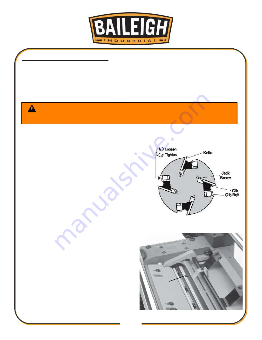
set cutterhead. This planer comes with jack screws for adjusting the height of the knives in the
cutterhead (Fig. 23).
1. UNPLUG OR DISCONNECT PLANER FROM POWER SOURCE AND LOCK OUT POWER.
2. Remove the top cover and dust port.
3. Remove the belt guard to expose the cutterhead
pulley.
4. Rotate the cutterhead pulley to expose the jack
screw access hole (A).
5. Loosen the cutterhead gib bolts, starting in the
middle, and alternating back and forth until all of
the gib bolts are loose, but not falling out.
6. Position the knife gauge over the knife as shown in
Figure 23 and loosen the gib bolts until the knife is
completely loose.
7. Find the jack screws through the access holes in
the cutterhead (Fig. 24) and rotate the jack screws
with a hex wrench to raise or lower the knife.
When the knife is set correctly, it barely
touches the middle pad of the knife setting
gauge. Snug the gib bolts tight enough to just
hold the knife in place. Repeat Steps 5-7 with
the rest of the knives.
8. Rotate the cutterhead to the first knife you
started with. Slightly tighten all the gib bolts,
starting at the ends and working your way to
the middle by alternating left and right. Repeat
this step on the rest of the knives.
9. Repeat Step 8 to final tighten each gib bolt.
WARNING:
Knife inserts are dangerously sharp. Use extreme caution
when working with or around the knife inserts.
Fig. 24
A
Fig. 23
Summary of Contents for IP-2511-HD
Page 39: ...36 36 ELECTRICAL SCHEMATIC...
Page 40: ...37 37...
Page 41: ...38 38...
Page 42: ...39 39...
Page 43: ...40 40 Electrical Cabinet Layout...
Page 44: ...41 41 CUTTERHEAD PARTS DIAGRAM...
Page 46: ...43 43 TABLE PARTS DIAGRAM...
Page 48: ...45 45 TABLE ROLLER PARTS DIAGRAM...
Page 50: ...47 47 INFEED PARTS DIAGRAM...
Page 52: ...49 49 STAND PARTS DIAGRAM...
Page 54: ...51 51 NOTES...
Page 55: ...52 52 NOTES...


