12
12
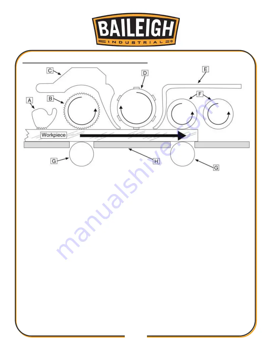
INTERNAL COMPONENT IDENTIFICATION
A.
Anti-Kickback Fingers:
Provide additional safety for the operator.
B.
Serrated Infeed Roller:
Pushes workpiece toward the cutterhead.
C.
Chipbreaker:
Breaks off chips created by the cutterhead to prevent tear out and diverts the
chips to the dust port.
D.
Spiral Cutterhead:
Holds the carbide inserts in a longitudinal spiral pattern that plane the
workpiece.
E.
Pressure Bar:
Stabilizes the workpiece as it leaves the cutterhead and assists in deflect- ing
wood particles toward the dust hood.
F.
Outfeed Rollers:
Pulls the workpiece toward the outfeed table.
G.
Table Roller:
Provide upward pressure on the workpiece enabling the feed rollers to pull
the workpiece along.
H.
Working Table:
Provides a smooth and level path for the workpiece as it moves through the
planer.
Fig. 3
Summary of Contents for IP-2511-HD
Page 39: ...36 36 ELECTRICAL SCHEMATIC...
Page 40: ...37 37...
Page 41: ...38 38...
Page 42: ...39 39...
Page 43: ...40 40 Electrical Cabinet Layout...
Page 44: ...41 41 CUTTERHEAD PARTS DIAGRAM...
Page 46: ...43 43 TABLE PARTS DIAGRAM...
Page 48: ...45 45 TABLE ROLLER PARTS DIAGRAM...
Page 50: ...47 47 INFEED PARTS DIAGRAM...
Page 52: ...49 49 STAND PARTS DIAGRAM...
Page 54: ...51 51 NOTES...
Page 55: ...52 52 NOTES...


