background image


32 

32 

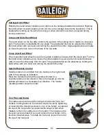
Carriage Hand Wheel 

Rotating the hand wheel clockwise (cw) will move the carriage towards the tailstock. Rotating 
the hand wheel counterclockwise (ccw) will move the carriage towards the headstock. This is 
helpful when setting up the lathe for turning or when manual movement is required during 
turning operations. 
 

Compound Slide Hand Wheel 

The hand wheel on the top slide controls the position of the cutting tool in relation to the piece 
part. The top slide is adjustable for any angle. The graduated dial can be adjusted by holding 
the hand wheel with one hand and turning the dial with the other. Angle adjustments are made 
by loosening the hex nuts on the base of the top slide. 
 

Cross slide Hand Wheel 

The cross slide hand wheel moves the top slide towards and away from the piece part. Turning 
the hand wheel clockwise (cw) moves the slide towards the piece part and counterclockwise 
(ccw) moves the slide away from the part. The graduated dial can be adjusted by holding the 
hand wheel with one hand and turning the dial with the other. 
 

Spindle Rotation Control 

Spindle rotation is controlled from the handle on the right-hand 
side of the carriage as indicated. 
Move the handle down and the spindle will rotate in a 
counterclockwise (ccw) direction. Move the handle up and the 
spindle will rotate in a clockwise (cw) direction. The middle 
(neutral) position stops the motor. 


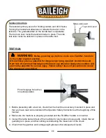
Tool Post and Holder 

This lathe comes with a quick-change tool post and (four) tool 
holders. Cutting tools can be secured and removed by tightening 
or loosening the clamping screws on top of the holder. Located at 
the top of the tool post is a knurled thumb wheel, which when 
rotated, centers the cutting tool in the holder. The handle on the 
tool post can be rotated to lock and unlock the tool holder in the 
tool post dovetail ways. To rotate the tool post, loosen the nut at 
the top of the tool post. 


Summary of Contents for PL-1340E-1.0

Page 1: ...TRIAL INC IS PROHIBITED Baileigh Industrial Inc does not assume and hereby disclaims any liability for any damage or loss caused by an omission or error in this Operator s Manual resulting from accide...

Page 2: ...OLS FOR OPERATION 18 Steady Rest 19 Live Center 19 Follow Rest 20 Tailstock 20 Faceplate 21 Quick Change Tool Posts 21 LATHE SETUP 22 Lubrication 22 Chucks 22 Chuck Removal 23 Chuck Installation 23 Fo...

Page 3: ...36 Lathe Alignment 37 V Belt Removal and Adjustment 39 LUBRICATION AND MAINTENANCE 40 Daily Maintenance 40 Weekly Maintenance 40 3 Month Maintenance 40 Oil Disposal 40 Accessing and Cleaning the Cool...

Page 4: ...e to Seller of any suspected defect in the Goods prior to the expiration of the warranty period The original end user must also obtain a RGA from Seller prior to returning any Goods to Seller for warr...

Page 5: ...or further remedies provided under this Agreement or at law or equity Attorney s Fees In the event legal action is necessary to recover monies due from Buyer or to enforce any provision of this Agree...

Page 6: ...Description of the functional parts of the machine Capacity charts Set up and start up instructions Machine operation Scheduled maintenance Parts lists GENERAL NOTES After receiving your equipment rem...

Page 7: ...es a hazard or unsafe practice that will result in severe Injury or Death Safety signs with signal word DANGER or WARNING are typically near specific hazards General precautions are listed on CAUTION...

Page 8: ...ect against objectionable or uncomfortable loud noises DUST HAZARD Wear appropriate dust mask Dust created while using machinery can cause cancer birth defects and long term respiratory damage Be awar...

Page 9: ...N In the event of incorrect operation or dangerous conditions the machine can be stopped immediately by pressing the E STOP button Twist the emergency stop button clockwise cw to reset Note Resetting...

Page 10: ...ny modifications or alterations to a Baileigh machine Modifications or alterations to a machine may pose a substantial risk of injury to the operator or others and may do substantial damage to the mac...

Page 11: ...are producing metal filings 15 Do not overreach Maintain proper footing and balance at all times DO NOT reach over or across a running machine 16 Stay alert Watch what you are doing and use common se...

Page 12: ...he piece part as necessary when it extends from the chuck using a lathe center in the tail stock or by using either a steady rest or a follow rest 33 When the chuck and piece part are in motion NEVER...

Page 13: ...m Maximum Tool Selection 625 x 625 16mm x 16mm Leadscrew Thread Pitch 8 T P I Longitudinal Feed Range 0 001 0 0137 rev 0 026 0 348 mm rev Cross Feed Range 0 0002 0 0037 rev 0 007 0 094 mm rev Metric T...

Page 14: ...age painted surfaces Follow manufacturer s label instructions when using any type of cleaning product After cleaning wipe unpainted metal surfaces with a light coating of quality oil or grease for pro...

Page 15: ...or jerky motion and maintain a safe clearance zone around the transport area Use a fork lift with sufficient lifting capacity and forks that are long enough to reach the complete width of the machine...

Page 16: ...n the precise placement of it to the mounting surface FLOOR This tool distributes a large amount of weight over a small area Make certain that the floor is capable of supporting the weight of the mach...

Page 17: ...plug on the right side of the apron Check the oil level in the oil gauge glass on the front regularly Change Gears Lubricate the change gears with thick machine oil or grease once a month Other Parts...

Page 18: ...cs as indicated on the tool All line connections should make good contact Running on low voltage will damage the motor In the event of a malfunction or breakdown grounding provides a path of least res...

Page 19: ...in disconnect switch on the control panel to the OFF position 2 Unlock and open the electrical enclosure door 3 Locate and install the main disconnect knob onto the switch shaft 4 Route a power cord i...

Page 20: ...Feed thread selector handle 4 Tool post clamping lever 14 Forward reverse switch 5 Compound rest lock 15 Feed rod 6 Cross slide lock 16 Longitudinal traverse handwheel 7 Carriage lock 17 Cross travers...

Page 21: ...alf nut opened Imperial thread Half nut closed Right hand thread and Longitudinal feed toward The headstock side Left figure Left hand thread and Longitudinal feed toward The headstock side Right figu...

Page 22: ...nd the chuck more than three times its diameter should be supported by the live center The barrel of the tailstock and the end of the live center have a Morse 3 taper Before inserting the live center...

Page 23: ...will need replacement when they wear out Tailstock The tailstock consists of the base base lock barrel barrel lock handwheel body and screw The tailstock on a lathe has many functions including suppor...

Page 24: ...l Included are 3 Model 250 201 holders and 1 Model 250 202 holder with a V groove in the bottom of the holder so it can also accommodate a boring bar The 250 200 tool post is the same as a BXA style T...

Page 25: ...o tolerance Both the 3 jaw chuck and the 4 jaw chuck have Camlock mounting Note that there are lines stamped on the cam and on the chuck These indicate whether the cam is in a locked position or an un...

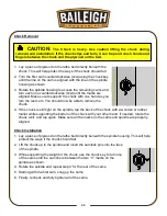
Page 26: ...ded rotate the chuck a bit and tap again Make sure all the marks on the cams and spindle are properly aligned Chuck Installation 1 Lay a piece of plywood on the lathe bed directly beneath the spindle...

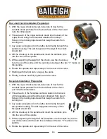
Page 27: ...spindle and repeat step 3 for the rest of the cams 7 Starting with the first cam snug up the cams 8 Finally recheck and fully tighten all of the cams Faceplate Installation Preparation 1 With the 3 ja...

Page 28: ...ise cw to reset Spindle Speeds IMPORTANT Never change spindle speeds while the motor or spindle is in motion The speed of the spindle is set by the position of the two speed control handles Handle 13...

Page 29: ...e As the chuck rotates the gears will align allowing the selector to engage Quick Change Selection Knobs The four knobs shown are used to change the feed rate or number of threads per inch This part o...

Page 30: ...nd R If using the metric chart the procedure would be the same This symbol indicates longitudinal feed This symbol indicates cross feed rates figure A figure B a 60T 120T a A B A B D D C C 3mm LEVER T...

Page 31: ...t washer to replace either gear a or gear b with another gear Note DO NOT place anything hard between the gears to prevent rotation or you could break the teeth 4 Loosening the clamp bolt and pivot nu...

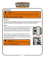
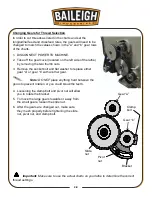
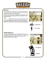
Page 32: ...re the half nut engagement lever 31 is disengaged at neutral position before operating the feed selector handle 33 There is an interlock mechanism between the auto feeding and the thread cutting engag...

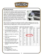
Page 33: ...tiple passes until the required depth is reached 1 Using the chart to cut 20 threads per inch engage the half nut when the 1 2 3 or 4 is at the indicator mark 2 You must determine how long you want th...

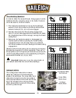
Page 34: ...There are 31 thread pitches each in Imperial and Diametric as well as 26 metric thread pitches which can be obtained by turning the feed selector handles 2 3 4 5 Important Make sure to use the actual...

Page 35: ...the slide towards the piece part and counterclockwise ccw moves the slide away from the part The graduated dial can be adjusted by holding the hand wheel with one hand and turning the dial with the o...

Page 36: ...is properly grounded and the Fwd Rev handle is in neutral 3 Inspect the lathe bed and rest of the machine for any tools and loose parts Check that all guarding is in place and that nothing is obstruct...

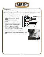
Page 37: ...the arrow It is important that the saddle gib be properly adjusted A loose gib can cause finish issues on a piece part and a gib that is adjusted too tight can cause premature wear The gib adjustment...

Page 38: ...as the Cross slide gib The gib on the Compound rest can be adjusted with the screw located at the tool post end The gib is wedge shaped and by loosening the screw closest to the operator and then tigh...

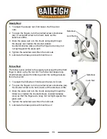
Page 39: ...low rest is similar to the steady rest except that the third finger is taken up by the tool bit The follow rest keeps long small diameter pieces from flexing under the cutting pressure from the tool b...

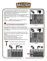
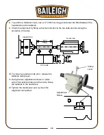
Page 40: ...x 10 254mm long 2 Span it in the chuck without using the tailstock 3 Cut off a chip over a length of 6 152mm 4 Measure and compare the diameters at Point A and Point B They should be the same 5 To cor...

Page 41: ...p slide and traversing the centerline of the bar 10 To correct any side to side error release the tailstock clamp lever 11 Using the two adjustment screws on either side of the tailstock base and the...

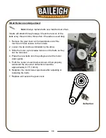
Page 42: ...to have access to the V belts 2 Loosen the two bolts as indicated by the arrow 3 Slide the motor up to release tension on the belts so they can be removed 4 Place the new belts onto the pulleys and le...

Page 43: ...Thoroughly clean the machine including the coolant tank On a weekly basis clean the machine and the area around it Lubricate threaded components and sliding devices Apply rust inhibitive lubricant to...

Page 44: ...ends tool and machine life Each gallon of concentrate makes 21 gallons of coolant Storing Machine for Extended Period of Time If the Lathe is to be inactive for a long period of time prepare the machi...

Page 45: ...ug 3 Fill the headstock reservoir by removing the fill plug 4 The first oil change should be made after 3 months and thereafter once a year with a Shell Tellus 68 viscosity gear oil or equivalent Capa...

Page 46: ...eafter once a year with a Shell Tellus 68 viscosity gear oil or equivalent Capacity is 0 8qt 0 8L Apron The apron is lubricated from an internal reservoir of oil 1 Ensure that the oil level shows 3 4...

Page 47: ...s as indicated daily Also oil the cross slide nut lead screw and slide ways with a light machine oil or way lubricant on a daily basis Note Use a bristle paint brush to clean the slide ways lead screw...

Page 48: ...45 45 ELECTRICAL DIAGRAM...

Page 49: ...0 52A 1 QF2 Circuit Breaker Control Switches DZ47 63 D3 1 QF3 Circuit Breaker Work Lamp DZ47 63 D6 1 EL Work Lamp JC52 1 SB1 E Stop Button LAY3 01ZS 1 SB2 Button LAY3 10 1 SA2 Selector Switch Coolant...

Page 50: ...47 47 THREAD AND FEED SELECTION Longitudinal and cross feed table Metric and imperial thread table Suitable for metric lead crew Suitable for imperial leadscrew...

Page 51: ...7 44 1 8 41 2 1 8 14 1 8 48 1 8 43 4 1 8 16 1 8 52 1 8 5 1 3 5 7 18 1 8 56 1 8 51 2 1 8 19 1 3 5 7 64 1 8 6 1 8 20 1 8 72 1 8 61 2 1 8 22 1 8 76 1 8 7 1 3 5 7 24 1 8 80 1 8 8 1 8 26 1 8 88 1 8 9 1 3...

Page 52: ...TOWOC WI 54220 PHONE 920 684 4990 FAX 920 684 3944 www baileigh com BAILEIGH INDUSTRIAL HOLDINGS LTD UNIT D SWIFT POINT SWIFT VALLEY INDUSTRIAL ESTATE RUGBY WEST MIDLANDS CV21 1QH UNITED KINGDOM PHONE...

Reviews: