30
30
Threading Dial Indicator
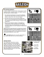
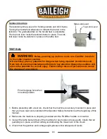
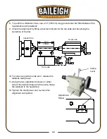
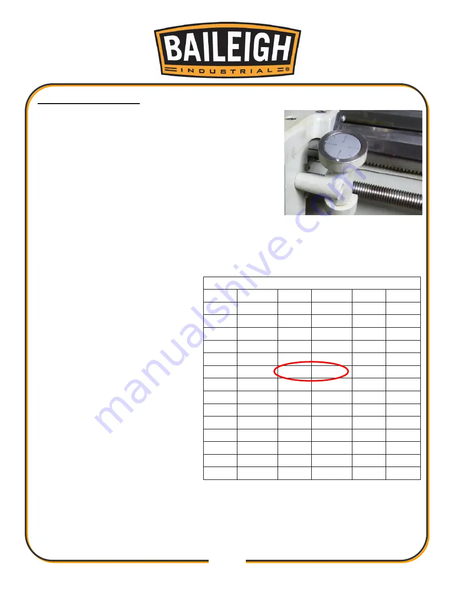
The threading dial indicator is located on the right-hand side
of the apron. It is used when cutting imperial threads and
tells you when to engage the half nut to begin the threading
process. The indicator face has eight lines and four numbers
printed on the dial. An indicator pin is located at the bottom
of the rim. The dial is mounted to a shaft that has a small
gear mounted at the opposite end. By loosening a socket
capscrew you can pivot the housing to either engage or
disengage from the leadscrew. When engaged, the dial will
turn as the spindle rotates. If the dial does not turn re-adjust
the housing position.
When the half nut is engaged, the dial stops turning. By carefully engaging the half nut as the
correct number or line passes by the indicator mark, a thread can be established and the lead
maintained through multiple passes, until the required depth is reached.
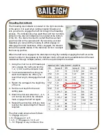
1. Using the chart to cut 20 threads per
inch, engage the half nut when the
1, 2, 3, or 4 is at the indicator mark.
2. You must determine how long you
want the thread to be. When you
reach that length, disengage the half
nut.
3. Return the carriage to the beginning
of the cut.
4. Set the next depth for the next
cutting pass.
5. Watch the dial and when the 1, 2, 3,
or 4 comes around to the indicator
mark, engage the half nut again.
6. Repeat the procedure until you have
reached the desired depth of thread
required.
The other scale values are as follows:
1 = Engage only on 1
1, 5 = Engage on 1 or 5
1, 3, 5, 7 = Engage on 1,3,5, or 7
1
– 8 = Engage on any number or line
INDICATOR TABLE WHIT WORTH
TPI
SCALE
TPI
SCALE
TPI
SCALE
4
1-8
13
1.3.5.7
44
1-8
41/2
1-8
14
1-8
48
1-8
43/4
1-8
16
1-8
52
1-8
5
1.3.5.7
18
1-8
56
1-8
51/2
1-8
19
1.3.5.7
64
1-8
6
1-8
20
1-8
72
1-8
61/2
1-8
22
1-8
76
1-8
7
1.3.5.7
24
1-8
80
1-8
8
1-8
26
1-8
88
1-8
9
1.3.5.7
28
1-8
96
1-8
91/2
1-8
32
1-8
104
1-8
10
1-8
36
1-8
112
1-8
11
1.3.5.7
38
1-8
12
1-8
40
1-8
Summary of Contents for PL-1340E-1.0
Page 48: ...45 45 ELECTRICAL DIAGRAM...

