31
31
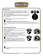
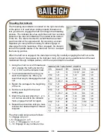
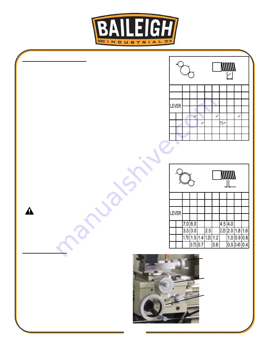
Thread Cutting Operation
In order to obtain the desired thread, change gears must be
installed correctly, using the values in the charts. Failure to
do so will result in incorrect threads.
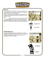
1. First rotate the leadscrew by moving the feed/thread
selector (33) to any position and making sure the feed
selector knobs (2), (3), (4), & (5) are engaged.
2. Operate downward, the thread cutting engagement
lever (31) and it will engage with the leadscrew to obtain
the longitudinal travel of the carriage; namely the thread
cutting feed.
3. Make sure the feed axis selector is disengaged (at
neutral position) before operating the thread cutting
engagement lever (31) because there is an interlock
mechanism between the auto feeding and thread cutting
engagement.
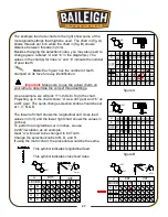
Direction of the thread cutting can be chosen by turning the
feed direction selector (10) at the headstock. There are 31
thread pitches each in Imperial and Diametric as well as 26
metric thread pitches which can be obtained by turning the
feed selector handles (2), (3), (4), & (5).
Important: Make sure to use the actual charts on
your lathe to determine the correct thread settings.
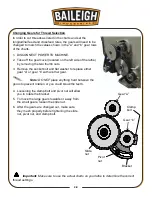
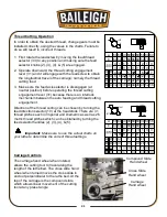
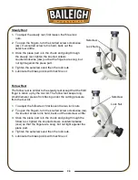
Carriage Controls
The carriage hand wheel when rotated,
allows the cutting tool to travel along the
length of the lathe bed. The cross slide hand
wheel when turned moves the cross slide in
and out perpendicular to the lathe bed. At the
top of the carriage is the compound slide
which allows linear movement of the cutting
tool at any preset angle.
Compound Slide
Hand wheel
Cross Slide
Hand wheel
Carriage
Hand wheel
T
1"
a
b
120T
60
60
4
V
4
16
32
60 60 60 60 60 56 60 60
54 57 60 66 69 54 78 63
1 1 1 1 1 2 1 3
V V V V V V V V
4
1
2
5 5
6 6
7
1
2
1
2
8
9
1
2
1
2
9
10 11
12 13 14
18
36
19
38
20
40
22
44
23
46
24
48
26
52
28
56
a
b
A
B
A
B
D
D
C
C
mm
a
b
120T
56
60
4
R
60 60 30 60 60 30 60 56
63
1 3 4 1 3 1 3 3
R S T V R T V V
a
b
A
B
A
B
D
D
C
C
127T
60 60 60 60 60 60 60
5
Summary of Contents for PL-1340E-1.0
Page 48: ...45 45 ELECTRICAL DIAGRAM...

