15
15
Die Installation
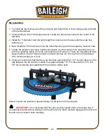
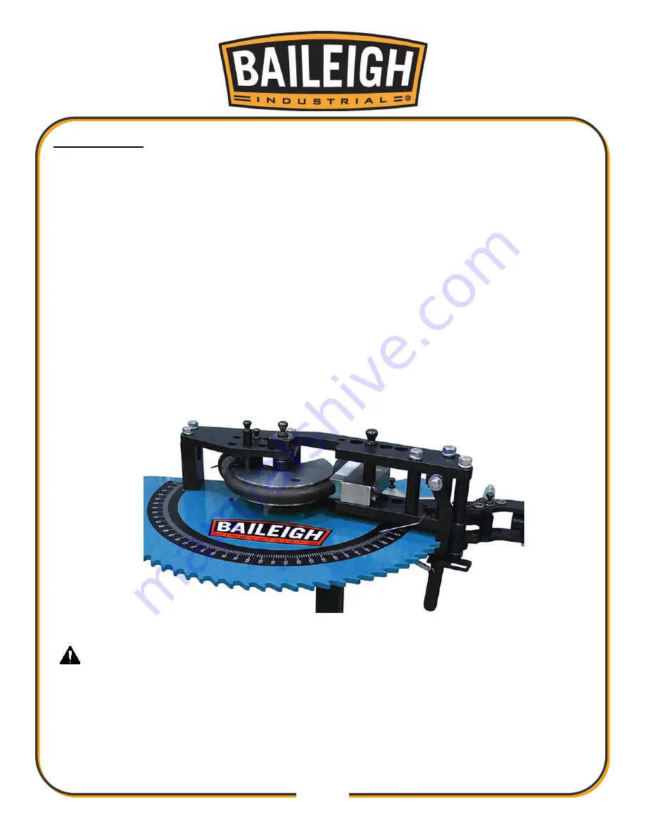
1. To install the die. Remove all of the pivot pins and install them in their storage area to the left
of the ratchet wheel.
2. Choose either a 90 or 180 degree die set. Locate the dies center hole with the center of the
machine.
3. Install the 1" diameter main die pin through the center and all the way until the snap ring
bottoms out.
4. Next install the 7/8" die drive pin into the holes that line up with the respective machine hole.
5. Locate the proper hook sleeve holder and position it so the center of the assembly lines up
with the centerline radius of the die and install the 3/4" hook pin. There are two different hook
sleeve holders. One for whole number nominal CLR dies (ie: 4.0 clr) and one for fractional
(0.5) increment dies (ie: 4.5 clr).
6. Choose a counter die that matches your bend die and install the 1-1/4" counter die pin so the
gap between the die and the counter die is approximately 1/8". For dies under 3.5 clr, the
3/4" die counterdie pin supplied with the machine will be used.
Correct counter die position is approximately 1/8' away from the forming die.
IMPORTANT:
It is critical that ail of the pins are fully seated down to the snap ring. If
you attempt to bend without making sure the pins are fully down machine damage will occur and
this will not be covered under warranty.
Summary of Contents for RDB-050
Page 1: ...OPERATOR S MANUAL ROTARY DRAW BENDER MODEL RDB 050 B8000 2015 Baileigh Industrial Inc ...
Page 13: ...11 11 GETTING TO KNOW YOUR MACHINE I B C E G D F H A ...
Page 27: ...25 25 Diagram 1 ...
Page 28: ...26 26 Diagram2 ...
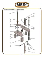
Page 30: ...28 28 TOP FRAME ASSEMBLY PARTS DIAGRAM ...
Page 32: ...30 30 RATCHET WHEEL ASSEMBLY PARTS DIAGRAM ...


