23
23
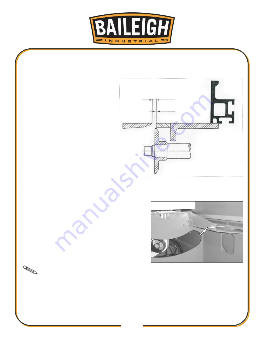
Check the parallelism of the sliding table to the main table.
7.
If the sliding table is parallel to the main table and has a maximum gap of 12mm between the
tables and 3mm to the spindle face, final tighten the 3 mounting bolts verifying that the table
does not move.
If the sliding table is either not parallel, or within the clearance limits:
Loosen the 3 screws holding the sliding table to the machine just enough to allow movement
8.
for adjustment.
Use the 2 adjusting screws at the ends of the main
9.
cabinet to make the sliding table parallel to the saw
blade and keep the gap within its limits.
Hold in position and fully tighten the 3 mounting
10.
bolts.
Note
The sliding table must be 0.3mm higher than the working table (The height
has been set at the factory. Do not adjust this height without verifed measerment and approval
from the factory. This is considered an unauthorized change and will void the warranty.
Maximum 12mm to main saw
Maximum 3mm to spindle face
Summary of Contents for STS-14120DRO
Page 55: ...51 51...
Page 56: ...52 52 Load Datum Values Only In ABS Mode A Description...
Page 57: ...53 53...
Page 58: ...54 54 B Load Datum...
Page 59: ...55 55 C Troubleshooting...
Page 60: ...56 56 Select Counting Direction...
Page 61: ...57 57...
Page 62: ...58 58 Set Device Resolution...
Page 63: ...59 59...
Page 64: ...60 60 Enable and Disable Specified Parameter...
Page 65: ...61 61...
Page 66: ...62 62...
Page 68: ...64 64 Parameter Setting...
Page 71: ...67 67 External Dimension Mounting Installation 10...
Page 73: ...69 69...
Page 74: ...70 70 B Troubleshooting...
Page 75: ...71 71...
Page 115: ...111 111 NOTES...


