31
31
MITER FENCE ASSEMBLE
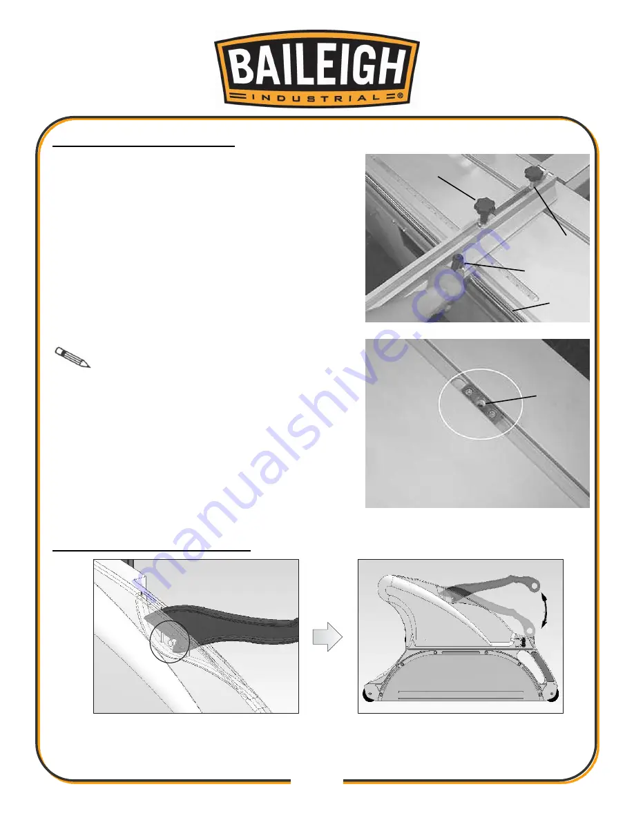
Loosen the miter fence slide block clamp handle (A)
1.
a few turns.
From the right end of the slide table, place the miter
2.
fence slide block over the round slide rod (B) on the
front of the sliding table and slide it onto the table
until it is over the angle scale.
Install the pivot bolt (C) into the pivot block (D) in
3.
the sliding table slot and tighten until the miter
fence is snug but will rotate on the pivot bolt.
Swing the miter fence to the desired angle and
4.
tighten the clamp handle (A).
Note
Swing the miter fence slowly and
smoothly as the slide block may bind slightly when the
fence is moved, especially at the extreme angles.
Loosen knob (E) and push outwards to extend the
5.
miter fence stops.
PUSH STICK INSTALLATION
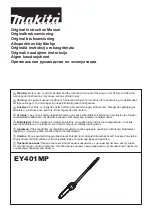
Install the pushing stick on the holder at degree 45.
1.
Lightly press down on the push stick until the push stick is latched in place.
2.
A
C
E
B
D
Summary of Contents for STS-14120DRO
Page 55: ...51 51...
Page 56: ...52 52 Load Datum Values Only In ABS Mode A Description...
Page 57: ...53 53...
Page 58: ...54 54 B Load Datum...
Page 59: ...55 55 C Troubleshooting...
Page 60: ...56 56 Select Counting Direction...
Page 61: ...57 57...
Page 62: ...58 58 Set Device Resolution...
Page 63: ...59 59...
Page 64: ...60 60 Enable and Disable Specified Parameter...
Page 65: ...61 61...
Page 66: ...62 62...
Page 68: ...64 64 Parameter Setting...
Page 71: ...67 67 External Dimension Mounting Installation 10...
Page 73: ...69 69...
Page 74: ...70 70 B Troubleshooting...
Page 75: ...71 71...
Page 115: ...111 111 NOTES...


