Procedure
WBPEEUI220771A0
PR14 - 3
□
2. Unplug all of the line cords from the AC outlets.
□
3. Switch the main power switch to the ON position.
□
4. Use the DMM, set to measure AC RMS voltage, to measure
the voltage at each of the AC outlets. The line voltage should be
90 to 132 VAC RMS for a 120-VAC input and 180 to 264 VAC
RMS for a 240-VAC input.
□
5. Use the DMM to check each AC outlet to insure that neu-
tral, live and ground are correctly wired, and that there are no
ground faults.
□
6. Switch the main power switch to the OFF position.
□
7. Use the DMM to verify that there is no power to any of the
AC outlets.
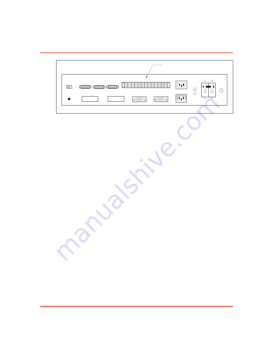
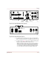
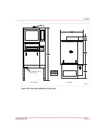
Figure PR14-4. Panel Mount Model PEP
T01476A
J2
I/O PWR
ADP PWR
FAN PWR
CPU INPUT PWR
POWER
W R IS T
S T R A P
PEP INPUT PWR
J1
KEYBOARD
RESET
DEGAUSS
ADP
2
NO
1
NO
2
NC
1
NC
2
CO
1
CO
4
NO
3
NO
4
NC
3
NC
4
CO
3
CO
6
NO
5
NO
6
NC
5
NC
6
CO
5
CO
DI
2+
DI
1+
DI
2-
DI
1-
DO
2+
DO
1+
DO
-2
DO
-1
ALARM CONTACTS
Summary of Contents for C-I-CV42C
Page 1: ...Bailey Hartmann Braun TM Instruction Conductor Conductor VMS Series 42 Auxiliary Terminal ...
Page 15: ...WBPEEUI220771A0 ...
Page 43: ...WBPEEUI220771A0 ...
Page 53: ...WBPEEUI220771A0 ...
Page 67: ...WBPEEUI220771A0 ...
Page 77: ...WBPEEUI220771A0 ...
Page 93: ...PR1 2 WBPEEUI220771A0 Procedure 3 Turn each end latch turn 4 Open the door ...
Page 97: ...WBPEEUI220771A0 ...
Page 107: ...WBPEEUI220771A0 ...
Page 113: ...WBPEEUI220771A0 ...
Page 123: ...WBPEEUI220771A0 ...
Page 125: ...WBPEEUI220771A0 ...
Page 133: ...WBPEEUI220771A0 ...
Page 137: ...WBPEEUI220771A0 ...
Page 141: ...WBPEEUI220771A0 ...
Page 143: ...WBPEEUI220771A0 ...
Page 145: ...WBPEEUI220771A0 ...
Page 147: ...WBPEEUI220771A0 ...
Page 151: ...WBPEEUI220771A0 ...
Page 177: ...PR27 6 WBPEEUI220771A0 Procedure 7 Install all cables onto the CPU ...
Page 181: ...WBPEEUI220771A0 ...
Page 185: ...WBPEEUI220771A0 ...
Page 195: ...WBPEEUI220771A0 ...
Page 197: ...WBPEEUI220771A0 ...
Page 213: ...WBPEEUI220771A0 ...


