background image

PR6 - 2


WBPEEUI220771A0

Procedure


6. Remove and label all cables from the module.

7. Pull out on the two tabs on each side of the module to 
release it.

8. Remove the module.

All Other Models

1. Verify that the main power switch is in the off position. 
Check the main power indicator to see if power is removed.

2. Label and remove all cables from the IIMKM02A module.

3. The IIMKM02A module has four retaining screws. Use the 
bladed screwdriver to remove the screws.

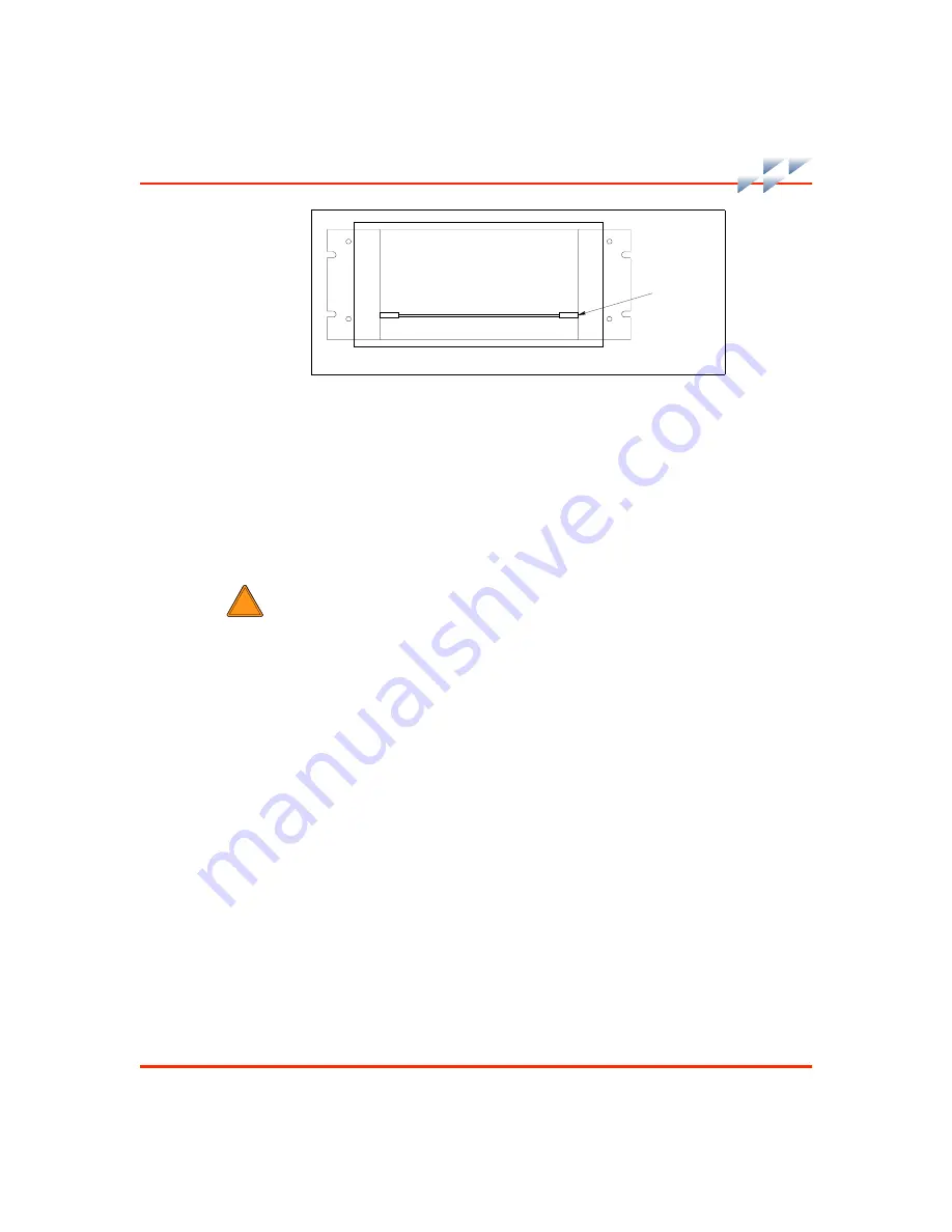
Figure PR6-1.  Module Location

T01446A

IIMKM02A

W1

Summary of Contents for C-I-CV42C

Page 1: ...Bailey Hartmann Braun TM Instruction Conductor Conductor VMS Series 42 Auxiliary Terminal ...

Page 2: ...the section and any nonprocedural informa tion This flowchart directs personnel to the appropriate proce dure located in the back of this instruction By treating each task as a separate entity the procedures provide an easy method for finding the information needed to perform each task The procedures can be removed and placed in separate folders or notebooks or carried to the job site The procedur...

Page 3: ...nal PR5 1 through PR5 5 Original PR6 1 through PR6 2 Original PR7 1 through PR7 3 Original PR8 1 through PR8 2 Original PR9 1 through PR9 4 Original PR10 1 through PR10 3 Original PR11 1 Original PR12 1 through PR12 2 Original PR13 1 through PR13 2 Original PR14 1 through PR14 3 Original PR15 1 through PR15 2 Original PR16 1 Original PR17 1 through PR17 3 Original PR18 1 Original PR19 1 Original P...

Page 4: ... Nomenclature 1 8 Specifications 1 8 Accessories 1 11 Section 2 Description and Operation 2 1 Introduction 2 1 Functional Operation 2 1 Section 3 Installation 3 1 Introduction 3 1 Special Handling 3 1 Unpacking and Inspection 3 2 Safety Considerations 3 3 Wiring Considerations 3 3 AC Power Wiring 3 4 Access 3 5 Connections 3 6 Communications Wiring 3 6 Access 3 6 Connections 3 6 Grounding 3 6 Soft...

Page 5: ... A Dimension Drawings A 1 Introduction A 1 Appendix B Factory Cabling B 1 Introduction B 1 Appendix C Quick Reference C 1 Introduction C 1 List of Procedures No Title PR1 Cover Removal PR2 Anchoring PR3 Connecting Console Components PR4 Wedge Table Installation PR5 Wiring PR6 Module Removal PR7 IIMKM02A Module Settings PR8 Module Installation PR9 Keyboard Interface Device Installation PR10 Etherne...

Page 6: ...lacement PR31 Keyboard Interface Assembly Replacement PR32 Upper Monitor Removal PR33 Lower Monitor Removal PR34 Touchscreen Removal PR35 Touchscreen Installation PR36 Upper Monitor Installation PR37 Lower Monitor Installation PR38 Touchscreen Controller Card Replacement PR39 Cover Installation List of Figures No Title Page 1 1 Table Top Model C I CV42C 1 1 2 1 2 Console Model Front View C I CV42C...

Page 7: ... Typical A 8 A 10 IICPI01 15 Wedge Table Dimensions A 9 A 11 IICPI02 45 Wedge Table Dimensions A 9 A 12 IICPI01 Work and Printer Surface Dimensions A 10 A 13 IICUC01 Utility Console Dimensions A 11 B 1 Table Top Model Factory Cabling B 3 B 2 Console Model Factory Cabling B 5 B 3 Environmental Model Factory Cabling B 7 B 4 Panel Mount Model Factory Cabling B 9 C 1 Table Top Model C 2 C 2 Console Mo...

Page 8: ...oystick Connection PR9 3 PR9 5 IIADP01 Installation PR9 4 PR10 1 Table Top and Console Model Cable Entry Cutouts PR10 2 PR10 2 Environmental Model Cable Entry Cutout PR10 3 PR12 1 Work Surface Installation PR12 2 PR13 1 Panel Mount Dimensions PR13 2 PR14 1 Table Top Model Keyboard Interface Assembly PR14 1 PR14 2 Console Model PEP PR14 2 PR14 3 Environmental Model PEP PR14 2 PR14 4 Panel Mount Mod...

Page 9: ...2 PR28 3 Environmental Model Keyboard Interface Assembly PR28 2 PR28 4 Environmental Model Joystick Connection PR28 3 PR29 1 IIADP02 Replacement PR29 2 PR29 2 IIADP02 Bezel Removal PR29 3 PR30 1 NADS03 Replacement PR30 2 PR30 2 NADS03 Switch Settings PR30 2 PR31 1 Keyboard Interface Assembly PR31 2 PR36 1 Monitor Connections and Adjustments PR36 2 PR37 1 Monitor Connections and Adjustments PR37 2 ...

Page 10: ...WBPEEUI220771A0 ix List of Tables continued No Title Pg B 4 Panel Mount Model Factory Cabling B 7 C 1 Quick Reference Figures C 1 PR7 1 IIMKM02A Module Jumper Settings PR7 1 PR11 1 Printers PR11 1 ...

Page 11: ... result in severe or fatal shock or equipment damage p PR17 1 PR19 1 PR20 1 PR21 1 PR23 1 Disconnect the AC line cord or power lines from the operating branch circuit coming from the source before attempting electrical connections Instruments powered by AC line voltage constitute a potential for personnel injury due to electric shock p PR5 1 Wear eye protection whenever working with cleaning solve...

Page 12: ...PECIFIC CAUTIONS On the keyboard interface connector board set positions 5 6 and 7 of dipswitch SW1 to closed on Set positions 1 through 4 and 8 of dipswitch SW1 to open off Failure to configure dipswitch SW1 properly will damage the CPU p PR31 1 ...

Page 13: ...riptions from equipment manuals Parts without a description must be ordered from the nearest sales or service office Recommended spare parts lists including prices are available though the nearest sales or service office Elsag Bailey has modern training facilities available for train ing your personnel On site training is also available Contact your nearest Elsag Bailey sales office for specific i...

Page 14: ...tered trademark of Elsag Bailey Process Automation Ethernet Trademark of Xerox Corporation HP Registered trademark of Hewlett Packard Company INFI NET Registered trademark of Elsag Bailey Process Automation Lexmark Trademark of Lexmark International Inc Mylar Registered trademark of E I DuPont de Nemours Company Incorporated Pink Pearl Registered trademark of Eberhard Faber Incorporated Tektronix ...

Page 15: ...WBPEEUI220771A0 ...

Page 16: ...al Intended User This instruction is intended for use by technical personnel responsible for the installation maintenance and repair of the auxiliary terminal System engineers and technicians with a background in pro cess control systems should read this instruction thoroughly before installing and using the system Do not put the auxil iary terminal into operation until reading and understanding t...

Page 17: ...nitor is mounted on top of the case and the keyboard interface assembly is located below the monitor The monitor can tilt and swivel The rear connector panel has an AC input alarm relays con nectors for monitor cables and a power switch The front panel has the connectors for peripheral operator input devices and a tune off configuration keyswitch The CPU is located inside the cabinet on a shelf Ac...

Page 18: ... ule in the multibus card cage The monitors annunciator dis play panel ADP and keyboard interface assembly are in the upper half of the auxiliary terminal The lower half contains the power supply CPU power entry panel PEP with cable connector panel and multibus card cage This model can have either a lower monitor C I CV42C 21 or an upper monitor C I CV42C 22 but not both Figure 1 2 Console Model F...

Page 19: ...ble entry is located at the rear of the auxiliary terminal Environmental Model C I CV42C 3 Figure 1 4 shows the environmental model of the auxiliary ter minal The environmental model contains a monitor power entry panel operator keyboard annunciator display panel and interface similar to the console model 19 inch panel mount and table top model Figure 1 3 Console Model Rear View C I CV42C 2 T01442...

Page 20: ... air conditioner provides internal cooling and the stainless steel exterior provides corrosion protection Panel Mount Model C I CV42C 4 The hardware of the panel mount model is located behind the monitor and keyboard interface assembly The power supply PEP CPU and IIMKM02A module are located with the monitor The keyboard interface assembly is mounted on a separate panel The alarm relays are for al...

Page 21: ...t may be used as a reference Introduction Presents an overview of the auxiliary terminal and related hardware It also provides a complete list of system specifications Description and Operation Describes the theory of operation of the auxiliary terminal and related hardware Installation Provides an introduction into the procedures involved in plac ing the auxiliary terminal into operation Provides...

Page 22: ...arious components Appendix B Factory Wiring Contains factory wiring diagrams and tables Appendix C Quick Reference Provides useful information including circuit board drawings showing the locations of specific components and switch and jumper settings Procedures PR1 through PR39 Provide procedures for each task How to Use this Instruction Read this entire instruction through in sequence before att...

Page 23: ...tify and describe the auxiliary terminal Specifications Table 1 3 contains the specifications for the C I CV42C auxil iary terminals Table 1 1 Reference Documents Number Document I E96 500 Site Planning and Preparation WBPEEUI220770A0 Conductor VMS Series 43 Workstation WBPEEUI220773A0 Operation Conductor VMS WBPEEUI220774A0 Configuration Conductor VMS WBPEEUI220775A0 File Utilities Conductor VMS ...

Page 24: ...r characteristics Power supply 5 VDC at 20 A 12 VDC at 4 A 12 VDC at 4 A Model Voltage Typical Amps Maximum Amps Typical Watts Maximum Watts C I CV42C 1 120 1 96 2 55 175 227 240 1 20 1 56 175 227 C I CV42C 2 120 1 80 2 34 158 205 240 1 11 1 44 162 211 C I CV42C 3 120 3 95 5 14 401 521 240 1 93 2 51 392 510 C I CV42C 4 120 1 96 2 55 175 227 240 1 20 1 56 175 227 Model Typical Inrush Current Amps C...

Page 25: ...Altitude Operating 10 to 40 C 50 to 104 F Nonoperating1 30 to 65 C 22 to 149 F Storage 5 to 50 C 41 to 122 F Operating 20 to 80 noncondensing Recommended minimum 40 Storage 10 to 95 noncondensing Operating 0 3 to 2 4 km 0 2 to 1 5 mi Cooling requirements Heat dissipation Table 1 3 Specifications continued Property Characteristic Value Alarm Relays Rating Contact voltage 24 VDC Overvoltage category...

Page 26: ...tic Value Model Height Width Depth cm in cm in cm in C I CV42C 1 55 80 22 00 49 53 19 50 60 96 24 00 C I CV42C 21 107 27 42 23 71 12 28 00 109 01 42 92 C I CV42C 22 156 94 61 78 71 12 28 00 109 01 42 92 C I CV42C 3 177 80 70 00 76 20 30 00 95 09 37 45 C I CV42C 4 614 10 24 17 116 00 45 67 94 97 37 39 Model Weight kg lbs C I CV42C 1 175 386 C I CV42C 21 164 360 C I CV42C 22 191 420 C I CV42C 3 240 ...

Page 27: ...ork and printer surface IIPRT02 Black and white printer IIPRT03 Color printer up to 64 colors IIPRT05 High speed black and white printer IIPRT08C Color black and white screen copy printer IIPRT09 24 pin color printer NOTE 1 Manufacturer part number Table 1 4 Accessories continued Accessory Description ...

Page 28: ...as schematics faceplates trends and alarm summaries For operating procedures refer to Table 1 1 Functional Operation The auxiliary terminal controls and monitors the process through the main workstation The auxiliary terminal is a remote operator station with a monitor and keyboard con trolled by a CPU Commands between the auxiliary terminal and the main workstation pass through an Ethernet networ...

Page 29: ...1 Block Diagram T01456A EN GINEERING KEYBOAR D JOYSTICK TOUC HSCREEN MOUSE TRAC KBALL AD P PANEL C I CV42C 3 ONLY NOT USED ON C I CV42C 3 OPERATOR KEYBOAR D IIM KM02A MODULE RGB KEYBOAR D INTER FACE ASSEMBLY CPU ETHERNET MONITOR NOT USED ON C I CV42C 3 ...

Page 30: ...fer to Table 1 4 is available for personnel working on components containing semiconductor devices It contains two wrist straps a ground cord assembly an alligator clip and a static dissipating work surface The intention is to connect the technician and the static dissipating work surface to the same ground point to prevent electrostatic discharge damage to the static sensitive devices When handli...

Page 31: ...live sys tem it should be done quickly Do not cut leads or lift circuit paths when troubleshooting 7 Be sure to ground any test equipment 8 Avoid static charges during removal and replacement Make sure the assembly is fully clean around its leads but do not rub or clean with an insulating cloth 9 Remove dust from components using an antistatic field service vacuum Do not use a lead graphite pencil...

Page 32: ...e the components when removing any fasteners that secure them to their ship ping pallets Never sit or stand on work surfaces or any other part of the auxiliary terminal Do not remove or install printed circuit boards or modules or components containing them with power applied This could damage the circuit board Remove power to all AC wiring when removing or connecting AC wires to prevent injury to...

Page 33: ... provides line filtering transient suppression and a 20 amp circuit breaker on the console and environmental models or a 10 amp circuit breaker on the panel mount model The location and part number of the PEP varies depend ing on the model The table top model does not use the PEP It has a rear connector panel with and IEC style AC input on the keyboard interface assembly The auxiliary terminal ope...

Page 34: ... degree Fahr enheit rating and thermoplastic insulation Wire with a 300 volt or 150 volt rating may be used if it is accepted by local wiring codes Wiring must be protected by cable trays or con duit and suited for the service voltage Power wiring to the auxiliary terminal must include a third wire grounding conductor This grounding conductor must not be a smaller gauge than the power wiring and m...

Page 35: ...onnections for the various models Grounding This instruction does not discuss the details of grounding sys tems Good grounding practices prevent problems and reduce system downtime A complete and properly grounded electrical system is vital for personnel safety equipment protections and normal process system operation Digital process control sys tems require a single point grounding system that ha...

Page 36: ...paths that apply before continuing At least one path must be completed Some blocks contain alphanumeric codes These codes identify the procedure that describes the steps to complete an indi cated task Complete all of the steps given in a procedure before continuing to the next procedure The procedures have check boxes in the margin by each proce dural step When performing a procedure check each bo...

Page 37: ...ETHERNET WIRING PRINTER INSTALLATION PR5 PR10 PR11 COVER INSTALLATION PR39 PR6 IIMKM02A MODULE SETTINGS PR7 KEYBOARD INTERFACE DEVICE INSTALLATION PR9 MODULE INSTALLATION PR8 USING TABLE TOP CABINET TO SUPPORT YES NO ANCHORING PR2 STAND ALONE OR ARRAY INSTALL PRINTERS ARRAY YES STAND ALONE NO CONNECTING CONSOLE COMPONENTS WEDGE TABLE INSTALLATION PR3 PR4 A ...

Page 38: ...E INSTALLATION PR12 MODULE REMOVAL WIRING PR5 PR6 MODULE INSTALLATION PR8 PRINTER INSTALLATION PR11 COVER INSTALLATION PR39 KEYBOARD INTERFACE DEVICE INSTALLATION PR9 IIMKM02A MODULE SETTINGS PR7 ETHERNET WIRING PR10 CONNECTING CONSOLE COMPONENTS WEDGE TABLE INSTALLATION PR3 PR4 ANCHOR CONSOLE YES NO STAND ALONE OR ARRAY INSTALL PRINTERS ARRAY STAND ALONE DONE ...

Page 39: ...6 PRINTER INSTALLATION PR11 COVER INSTALLATION PR39 ANCHORING PR2 INSTALL PRINTERS DONE IIMKM02A MODULE SETTINGS PR7 MODULE INSTALLATION PR8 KEYBOARD INTERFACE DEVICE INSTALLATION PR9 ETHERNET WIRING PR10 TR1425A D NO YES PANEL MOUNTING MODULE REMOVAL PR13 PR6 PRINTER INSTALLATION PR11 WIRING PR5 INSTALL PRINTERS DONE IIMKM02A MODULE SETTINGS PR7 MODULE INSTALLATION PR8 KEYBOARD INTERFACE DEVICE I...

Page 40: ...g personnel to the appropriate procedures NOTE Put circuit boards containing MOS devices into antistatic bags when stored or shipped back to the factory Do not repair circuit boards in the field All repairs and adjustments should be performed by qualified personnel Troubleshooting Table 4 1 is a general troubleshooting guide If the general troubleshooting guide does not eliminate the problem refer...

Page 41: ...te all of the steps given in a procedure before continuing to the next procedure The procedures have check boxes in the margin by each proce dural step When performing a procedure check each box as each step is completed By treating each task as a separate entity the procedures pro vide an easy method for finding the information needed to per form each task in the troubleshooting sequence Start up...

Page 42: ...A0 4 3 Figure 4 1 Troubleshooting Sequence TR1426A NO NO YES YES COVER INSTALLATION CONTACT LOCAL EBPA SERVICE OFFICE PR39 INSTALL COVERS STILL PROBLEMS DONE START DC POWER TEST AC POWER TEST PR15 PR14 NO YES COVER REMOVAL PR1 REMOVE COVERS ...

Page 43: ...WBPEEUI220771A0 ...

Page 44: ...ility of that product Elsag Bailey recommends that all equipment users practice a preventive maintenance program that will keep the equipment operating at an optimum level The procedures referred to in this section contain instructions that the customer should be able to perform on site These pre ventive maintenance procedures should be used as a guideline to assist in establishing good preventive...

Page 45: ...re turning With power off wipe dust off all fan blades N A 1 month Check cabinet and modules for dust Clean as necessary using an anti static vacuum N A 3 months Check power supply outputs Adjust power supplies if needed PR14 PR15 Check the air filters Clean or replace them as necessary Check the air filter more often in excessively dirty environments N A 6 months Check all signal power and ground...

Page 46: ...ng with the sequence In some cases more than one path can be taken during repair and replace ment procedures For paths that are in parallel either com plete all of the tasks in all of the paths before continuing or complete all of the tasks in only those paths that apply before continuing At least one path must be completed Some blocks contain alphanumeric codes These codes identify the procedure ...

Page 47: ...r and Replacement Sequence Figure 6 1 Repair and Replacement Sequence Flowchart TR1428A START WHAT AREA OF WORKSTATION MODULE AND MULTIBUS CARD CAGE POWER SUPPLY AND PEP CPU OPERATOR INTERFACE MONITORS AND TOUCHSCREEN A B C D E ...

Page 48: ... MODULE INSTALLATION PR 8 MULTIBUS CARD CAGE INSTALLATION PR 23 DONE SW ITCH ON POW ER AT PEP COVER INSTALLATION PR 39 REPLACING FAN OR MULTIBUS CARD CAGE REPLACING M ODULE OR MULTIBUS CARD CAGE COMPONENTS FAN MULTIBUS CARD CAGE MODULE COMPONENTS MULTIBUS CARD CAGE COMPONENTS CONSOLE MODEL ONLY MODULE REMOVAL PR 6 IIMKMO2A MODULE SETTINGS PR 7 MODULE INSTALLATION PR 8 NO YES INSTALL COVERS YES NO ...

Page 49: ...ER AT OPERATING BRANCH CIRCUIT SWITCH OFF POWER AT PEP TR1429A SWITCH ON POWER AT OPERATING BRANCH CIRCUIT SWITCH ON POWER AT PEP B COVER REMOVAL PR1 POWER SUPPLY REMOVAL POWER SUPPLY INSTALLATION PR24 PR25 PEP REPLACEMENT PR26 DONE COVER INSTALLATION PR39 NO YES INSTALL COVERS YES NO REMOVE COVERS ...

Page 50: ...cement Sequence WBPEEUI220771A0 6 5 Figure 6 4 CPU TR1430A SWITCH ON POWER AT PEP SWITCH OFF POWER AT PEP C COVER REMOVAL CPU REPLACEMENT PR1 PR27 DONE COVER INSTALLATION PR39 NO YES INSTALL COVERS YES NO REMOVE COVERS ...

Page 51: ...ION SWITCH ON POWER AT PEP D COVER REMOVAL COVER REMOVAL COVER REMOVAL KEYBOARD INTERFACE DEVICE REMOVAL IIADP02 REPLACEMENT NADS03 REPLACEMENT PR1 PR1 PR1 POWER SUPPLY REMOVAL PR24 PR28 KEYBOARD INTERFACE ASSEMBLY REPLACEMENT PR31 KEYBOARD INTERFACE DEVICE INSTALLATION PR9 PR29 PR30 PR28 PR9 REPLACE WHAT KEYBOARD MOUSE TRACKBALL IIADP01 IIADP02 NADS03 KEYBOARD INTERFACE ASSEMBLY POWER SUPPY INSTA...

Page 52: ...TOR REMOVAL LOWER MONITOR INSTALLATION UPPER MONITOR INSTALLATION TOUCHSCREEN REMOVAL TOUCHSCREEN REMOVAL TOUCHSCREEN INSTALLATION TOUCHSCREEN INSTALLATION PR33 PR37 PR36 PR34 PR34 PR35 PR35 UPPER MONITOR REMOVAL PR32 UPPER OR LOWER MONITOR UPPER CONSOLE MODEL ONLY LOWER REPLACE WHAT TOUCHSCREEN INSTALLED TOUCHSCREEN INSTALLED MONITOR TOUCHSCREEN TOUCHSCREEN CONTROLLER CARD NO NO YES YES DONE COVE...

Page 53: ...WBPEEUI220771A0 ...

Page 54: ...ibus keyboard module NADS03 Annunciator display panel 1947419 7 Fan 11 43 cm 4 1 2 in 1948623 9 Monitor 19 inch 1948802 3 Keyboard enclosure 1948803 2 Joystick 1949009 1 50 Ω thinwire terminator 6638353 5 Power entry panel 6638514 1 Keyboard Mylar operator 6638514 2 Keyboard Mylar operator 6638553 5 Power supply 6638554 2 Keyboard interface assembly 6638720 4 Lower monitor brightness cable 6638720...

Page 55: ...odel XP400 194776 11001 Fuse 1 A keyboard interface front panel 1948182 22001 Fuse 2 A 250V fast acting keyboard interface board NOTES 1 Includes keyboard interface assembly 2 Requires IIAKB04 keyboard without adapter Table 7 1 Spare Parts Recommended continued Nomenclature or Part Number Description C I CV42 1 2 3 4 ...

Page 56: ...and Dimension Drawings Figure Number Description A 1 Table top model dimensions A 2 Console model dimensions A 3 Environmental model dimensions A 4 Environmental model dimensions A 5 Panel mount model dimensions A 6 Table top and console model anchoring dimensions A 7 Anchoring scheme typical A 8 Table top and console model cable entry cutouts A 9 Array installation drawing typical A 10 IICPI01 15...

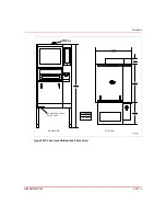
Page 57: ...A 2 WBPEEUI220771A0 Introduction Figure A 1 Table Top Model Dimensions T01457A Bailey 495 3 19 5 482 6 19 0 558 8 22 0 495 3 19 5 DIMENSIONS MILLIMETERS INCHES ...

Page 58: ...ole Model Dimensions T01491A 711 2 28 00 1085 7 42 75 1568 3 61 74 724 6 28 53 471 8 18 58 830 4 32 69 1090 1 42 92 DIMENSIONS MILLIMETERS INCHES STUD CENTER 482 6 19 00 66 0 2 60 281 8 11 09 TO REAR DOOR STUD CENTER 493 8 19 44 108 7 4 28 108 7 4 28 ...

Page 59: ...0 Introduction Figure A 3 Environmental Model Dimensions T01472A EYEBOLT REMOVABLE CONDUIT AND CABLE ENTRY AREA FRONT VIEW TOP VIEW 762 0 30 00 1778 0 70 00 777 9 30 63 96 9 3 82 381 0 15 00 DIMENSIONS MILLIMETERS INCHES ...

Page 60: ...UI220771A0 A 5 Figure A 4 Environmental Model Dimensions DIA MTG BOLTS 4 REQUIRED T01473A DIMENSIONS MILLIMETERS INCHES 472 5 18 60 12 7 0 50 SPLASH GUARDS AIR FILTER 430 3 16 94 711 2 28 00 707 4 27 85 MTG CTRS MTG CTRS ...

Page 61: ...25 95 3 3 75 8 7 0 38 228 6 9 00 374 7 14 75 114 3 4 50 457 2 18 00 101 6 4 00 MINIMUM SIDE CLEARANCE BOTH SIDES 472 9 18 62 94 0 3 70 152 4 6 0 76 2 3 00 6 4 4 HOLES 0 250 7 9 6 HOLES 0 312 196 9 MINIMUM TOP CLEARANCE DIMENSIONS MILLIMETERS INCHES KEYBOARD MOUNTING HOLE PATTERN 135 9 5 35 368 3 14 50 4 8 4 HOLES 0 19 Figure A 6 Table Top and Console Model Anchoring Dimensions DIMENSIONS MILLIMETE...

Page 62: ...OLT FLOOR OPENING FLOOR OPENING STANDARD FLOOR MOUNTING OPTIONAL WELD MOUNTING 101 6 4 00 38 1 1 50 DIMENSIONS MILLIMETERS INCHES Figure A 8 Table Top and Console Model Cable Entry Cutouts 197 1 7 76 129 5 5 10 REAR CABLE ENTRY BOTTOM CABLE ENTRY AREA 68 6 2 70 149 4 5 88 DIMENSIONS MILLIMETERS INCHES 63 5 2 50 T01444A ...

Page 63: ...stallation Drawing Typical 1000 0 39 40 711 2 28 00 15 REF 1054 1 41 50 482 6 19 00 52 8 2 08 69 2 2 73 1089 4 42 89 1270 0 50 00 215 7 8 49 T01418A 529 1 20 83 404 2 15 91 493 8 19 44 217 4 8 56 RECOMMENDED CLEARANCE FROM WALL FOR SERVICING AND AISLEWAY ...

Page 64: ...nsions T01295A IICPI01 482 6 19 00 52 8 2 08 69 3 2 73 50 8 2 00 404 1 15 91 493 8 19 44 335 3 13 20 DIMENSIONS MILLIMETERS INCHES 493 8 19 44 T01296A IICPI02 DIMENSIONS MILLIMETERS INCHES 395 7 15 58 254 5 10 02 615 4 24 23 50 8 2 00 956 6 37 66 885 2 34 85 791 5 31 16 493 8 19 44 482 6 19 00 1089 7 42 90 482 6 19 00 ...

Page 65: ...DED CLEARANCE FROM WALL FOR SERVICING AND AISLEWAY CABLE ACCESS COVER PLATE BOTTOM CABLE ENTRY AREA REAR CABLE ENTRY 1000 0 39 40 1090 1 42 92 433 7 17 08 1523 9 60 00 711 2 28 00 465 1 18 31 614 7 24 20 149 4 5 88 203 2 8 00 129 5 5 10 68 6 2 70 63 5 2 50 492 1 19 37 DIMENSIONS MILLIMETERS INCHES FRONT BACK 687 5 27 07 738 3 29 07 T01407A ...

Page 66: ...20771A0 A 11 Figure A 13 IICUC01 Utility Console Dimensions 1090 1 42 92 711 2 28 00 1000 0 39 40 1732 51 68 21 1085 7 42 75 687 5 27 07 T01493A SIDE FRONT REAR RECOMMENDED CLEARANCE FROM WALL FOR SERVICING AND AISLEWAY TOP ...

Page 67: ...WBPEEUI220771A0 ...

Page 68: ...Table B 1 Table Top Model Factory Cabling Cable No Fig B 1 Part No Connect From Connect To 1 6642339 1 J2 on chassis Keyboard port on CPU 2 6640778 1 J1 on chassis 0 port on CPU 3 6634512 26N15 P6 on IIMKM02A module Terminal block on chassis 4 6634512 26N15 P5 on IIMKM02A module P1 on keyboard interface assembly 5 6634512 26N15 P7 on IIMKM02A module P8 on keyboard interface assembly 6 6638719 2 P4...

Page 69: ...e J2 on chassis inside 15 6642341 1 J3 on chassis Mouse port on CPU 16 6642342 1 Touchscreen J5 on chassis inside 17 Power cable AC IN on CPU AC OUT on chassis 18 1949448 1 Monitor port on CPU RGB on chassis Table B 1 Table Top Model Factory Cabling continued Cable No Fig B 1 Part No Connect From Connect To ...

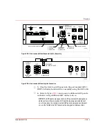
Page 70: ...N72 P6 on IIMKM02A module Rear of terminal block on PEP T01467A FAN R ESET SW ITCH P2 PO W ER SUPPLY MO NITO R MO NITOR BEZEL IIMKM02A MODULE KEYBO ARD INT ERFACE ASSEMBLY OPERATOR KEYB OARD M O USE TRACK BALL OPTIONAL TABLETOP ADP PAN EL ENGINEERING KEYBOAR D TO UCHSCREEN CPU P3 RGB P6 P9 J1 TERM BLK J3 J5 J2 P1 1 7 13 4 10 10 15 16 2 8 14 5 11 17 3 9 9 9 6 18 J4 AC OUT AC IN DEGAUSS VIDEO CABLE ...

Page 71: ...42341 1 P10 on keyboard interface assembly Mouse port on CPU 16 6640113 4 P3 on power supply P3 on IIMKM02A module 17 6640368 1 P5 on DC distribution board P5 on backplane 18 6640368 1 P6 on DC distribution board P6 on backplane 19 6640369 1 P2 on power supply Terminal block on DC distribu tion board 20 6640640 2 P7 on DC distribution board Cable P2 to fan on card cage 21 6640640 3 P8 on DC distri...

Page 72: ...n IIMKM02A module T01466A KEYBOARD INTERFACE ASSEMBLY CPU MONITOR MONITOR BEZEL PEP IIMKM02A MODULE TOUCHSCREEN POWER SUPPLY BACKPLANE ADP DC DISTR BOARD OPERATOR KEYBOARD MOUSE TRACKBALL OPTIONAL TABLETOP ADP PANEL ENGINEERING KEYBOARD TERM BLK TERM BLK AUX PORT AUX KBD MOUSE TRACK BALL KEY BOARD P8 KEYBOARD POWER CABLE VIDEO CABLE 0 PORT AC IN AUX OUT MONITOR AC LINE RGB BRIGHTNESS CONTRAST ETHE...

Page 73: ...ard interface assembly 11 6639212 2 J1 on PEP P1 on power supply 12 6639213 1 P3 on IIMKM02A module P3 on power supply 13 6639513 1 Terminal block on DC distribu tion board P2 on power supply 14 6640778 2 Touchscreen 1 port on CPU 16 Power cable AC IN on CPU AC POWER OUT on PEP 17 1949448 1 Monitor port on CPU RGB on monitor 18 Supplied with air conditioner AC OUT on PEP Air conditioner 19 Supplie...

Page 74: ...IR CONDITIONER OPERATOR KEYBOARD NOT USED OPTIONAL TABLETOP ADP PANEL ENGINEERING KEYBOARD AUX PORT AUX KBD MOUSE TRACK BALL KEY BOARD P8 P4 P1 P3 P1 19 16 8 17 9 1 ETHERNET NETWORK MOUSE P4 P2 P3 P1 P6 P5 P7 P8 P9 P16 P3 P2 P1 RGB AC IN CABLE INCLUDED WITH JOYSTICK POWER CABLE VIDEO CABLE MONITOR 0 PORT 1 PORT KEYBOARD PORT AC IN BRIGHTNESS CONTRAST DEGAUSS J1 RESET SW TERM BLK POWER AC IN AC OUT...

Page 75: ...9 6639352 1 P2 on keyboard interface assembly I O power port on chassis 10 6640112 2 P2 on power supply Line filter and E1 chassis ground 11 6640113 1 P3 on IIMKM02A module P3 on power supply 12 6640164 1 P1 on power supply P16 on IIMKM02A module and KYBD ADP FAN ports on chassis 13 6640778 2 Touchscreen 1 port on the CPU 14 Power cable AC POWER IN on CPU Power out on chassis and line filter 15 19...

Page 76: ... H P1 P3 P 2 AC IN A C IN DE GA US S BU TTO N BRIG HTNE S S CO NTR AS T R GB A DP A UX P O RT A UX KB D M OUS E TRA CK B A LL KE Y B O ARD P10 P 8 P 1 T01464A 12 6 11 TO A C P OW E R P OW ER CA B LE CPU IIMKM02A MODULE VIDE O C ABLE P OW ER A C IN M OU SE M ON ITOR E THER NE T NE TW OR K 0 P OR T K EYB OA RD 1 P OR T J1 J2 P 9 P 4 P 16 P 3 P 6 P8 P 5 P 7 A DP KE YBO AR D TE RM INAL BLO CK 5 3 9 10...

Page 77: ...WBPEEUI220771A0 ...

Page 78: ...er Description C 1 Table top model C 2 Console model front view C 3 Console model rear view C 4 Environmental model C 5 Panel mount model C 6 Table top model connections C 7 Console model PEP C 8 Environmental model PEP C 9 Panel mount model PEP C 10 IIMKM02A module C 11 Table top model keyboard interface assembly C 12 Console and panel mount model keyboard interface assembly C 13 Environmental mo...

Page 79: ... 2 WBPEEUI220771A0 Introduction Figure C 1 Table Top Model T01453A Bailey CPU WORK SURFACE MOUSE KEYBOARD CABINET POWER SUPPLY AND IIMKM02A MODULE LOCATED INSIDE CASE KEYBOARD INTERFACE ASSEMBLY MONITOR ...

Page 80: ...duction WBPEEUI220771A0 C 3 Figure C 2 Console Model Front View T01441A FRONT VIEW MULTIBUS CARD CAGE PEP IIMKM02A MODULE CD ROM DRIVE KEYBOARD INTERFACE ASSEMBLY LOWER MONITOR UPPER MONITOR ADP KEYBOARD CPU ...

Page 81: ...C 4 WBPEEUI220771A0 Introduction Figure C 3 Console Model Rear View T01442A REAR VIEW POWER SUPPLY PEP DC DISTRIBUTION BOARD KEYBOARD INTERFACE ASSEMBLY ADP MULTIBUS CARD CAGE UPPER MONITOR CPU ...

Page 82: ...ion WBPEEUI220771A0 C 5 Figure C 4 Environmental Model T01454A NADS03 MONITOR IIMKM02A MODULE PEP POWER SUPPLY AND KEYBOARD INTERFACE ASSEMBLY ENGINEERING KEYBOARD JOYSTICK OPERATOR KEYBOARD FRONT VIEW SIDE VIEW ...

Page 83: ...DULE AND POWER SUPPLY CPU SPLIT TOP COVER MONITOR KEYBOARD INTERFACE ASSEMBLY TUNE OFF CONFIG KEYBOARD AUX 1 PORT MOUSE TRACKBALL AUX KBD T01469A 2 N C 1 N C 4 NC 3 NC 6 NC 5 NC 2 CO 1 CO 4 C O 3 C O 6 C O D I 2 D I 1 D O 2 D O 1 DI 2 DI 1 DO 2 DO 1 5 C O 2 NO 1 NO 4 N O 3 N O 6 NO 5 NO DEGAUSS WRIST WRAP RESET R J3 J4 J1 J2 AC IN AC OUT J5 F1 G B ...

Page 84: ...NO 2 NC 1 NC 4 NC 3 NC 6 NC 5 NC 2 COM 1 COM 4 COM 3 COM 6 COM DI 2 DI 1 DO 2 DO 1 DI 2 DI 1 DO 2 DO 1 5 COM L DEGAUS S R E S E T L N L2 NOT USED Figure C 8 Environmental Model PEP T01474A KEYB OA RD RELAY ALARM CONTACTS GROUNDING CONDUCTOR E1 CHASSIS GROUND M AIN POW ER O FF TU NE C ON FIG DEGAUSS MAIN PO WER L N L2 WARNING MAY CAUSE SEVERE DAMAGE AIR CONDITIONING ONLY WARNING MAY CAUSE SEVERE DA...

Page 85: ...DI 1 DO 2 DO 1 DO 2 DO 1 ALARM CONTACTS Figure C 10 IIMKM02A Module Figure C 11 Table Top Model Keyboard Interface Assembly T01478A J6 J9 J8 J7 1 2 3 J2 FA CTORY SETTINGS CUSTOM ER SETTINGS J4 J 9 J 8 J 2 J 1 J3 J6 J7 J 5 1 2 3 1 2 3 1 2 3 1 2 3 1 2 3 1 2 3 3 2 1 J1 FACTORY SETTINGS CUSTOM ER SETTIN GS J4 1 2 3 1 2 3 FA CTORY SE TTINGS CUSTOM ER SETTINGS J3 1 2 3 1 2 3 FAC TORY SETTINGS CUSTOM ER ...

Page 86: ...4A KEYB OA RD RELAY ALARM CONTACTS GROUNDING CONDUCTOR E1 CHASSIS GROUND M AIN POW ER O FF TU NE C ON FIG DEGAUSS MAIN PO WER L N L2 WARNING MAY CAUSE SEVERE DAMAGE AIR CONDITIONING ONLY WARNING MAY CAUSE SEVERE DAMAGE SWITCH MUST BET SET FOR PROPER VOLTAGE AUX 1 PORT AUX KBD WRIST STRAP 120 240 VAC CRT 120 240 LIGHT 120 V TERMINAL 120 240 A C 120 V MOUSE TRACKBALL GROUNDED NEUTRAL CONDUCTOR CURRE...

Page 87: ...THERNET NETWORK CABLE AUX OUT AC IN 1 0 ON OFF POWER SWITCH T01302A TO AUX 1 PORT ON KEYBOARD INTERFACE BOARD P1 BACK OF ADP PANEL ADDRESS SWITCH PC BOARD ADDRESS SWITCH SETTINGS SW1 1 2 3 4 5 6 7 8 1 2 3 4 5 6 7 8 1 2 3 4 5 6 7 8 1 2 3 4 5 6 7 8 OPEN OPEN OPEN OPEN SW1 SW1 SW1 ADP 1 ADP 2 ADP 3 ADP 4 P1 SW1 P1 P2 P2 P2 ADP 2 ADP 3 ADP 4 1 2 3 4 5 6 7 8 OPEN ...

Page 88: ...6 Multibus Card Cage Backplane T01305A FAN 5 5 12 12 12 12 COM COM P5 P6 Figure C 17 IIADP02 ADP Switch Settings T01303A BACK OF ADP PANEL BEZEL SCREWS 2 ADDRESS SWITCH PC BOARD SW1 TO MKM BOARD 26 PIN P2 P4 P1 POWER IN CABLE 8 7 6 5 OPEN 4 3 2 1 ...

Page 89: ...roduction Figure C 18 NADS02 ADP Switch Settings T01477A ANNUNCIATOR DISPLAY PANEL ADP ADDRESS SWITCH SETTINGS TO MKM BOARD 26 PIN P2 P1 COM N C 5 PIN 1 POWER IN CABLE ADP 1 SW1 BACK OF ADP PANEL ADDRESS SWITCH SW1 PC BOARD P3 ...

Page 90: ...2 BLU RED YEL 5V GND 12V 12V SW1 F2 F1 F3 J1 P3 KEYBOARD AUX 1 PORT AUX KBD MOUSE TRACKBALL P4 P5 P6 P2 P8 ASSY 6638238 1 SW1 SWITCHES 5 6 AND 7 ARE CLOSED ON TP P3 ON DC DISTRIBUTION BOARD F1 F2 AND F3 ARE 2 A 250 V FAST BLOW TO P7 ON MKM BOARD AND TO P2 ON ADP BOARD P9 NOT USED P10 TO MOUSE PORT ON CPU CAUTION SWITCHES 5 6 AND 7 ARE CLOSED ON SWITCHES 1 THROUGH 4 AND 8 ARE OPEN OFF IF THEY ARE N...

Page 91: ...01479A P14 W 3 W 4 W 2 W 1 P15 P14 P15 CO NNECTOR PINS PLUG INTO M KM BOARD FACTORY SET DO N OT CHANG E TO SERIAL PORT 1 ON C PU TO UCH SCREEN CABLE M OUNTING HO LES 4 W 1 INSTALLED W 2 N OT INSTALLED R3 1 5 S1 S2 S1 8 7 6 5 4 3 2 1 S2 4 3 2 1 CLOSED O N CLOSED O N IIM KM 02A ...

Page 92: ...nvironmental model Console Model Front and Rear Doors 1 Insert the key into the lock and turn it turn counter clockwise 2 Pull down and out on the doors to remove them Top Cover 1 Use the inch Allen wrench to remove the five Allen screws that secure the top cover to the auxiliary terminal 2 Remove the top cover Environmental Model There are three latches on each door on the environmental model 1 U...

Page 93: ...PR1 2 WBPEEUI220771A0 Procedure 3 Turn each end latch turn 4 Open the door ...

Page 94: ...supplied with stabilizers no further securing methods are required If there are not stabilizers they must be securely anchored to the floor The environmental model must always be securely anchored to the floor If the control room has a raised false floor the anchoring mechanism must not be fastened to the false floor Figure PR2 1 shows the location of the customer mounting holes for the console mo...

Page 95: ...TERS INCHES T01443A 482 6 19 00 12 7 MM 0 50 IN CUSTOMER MOUNTING HOLES 493 8 19 44 66 0 2 60 108 7 4 28 Figure PR2 2 Environmental Model Anchoring Dimensions DIA MTG BOLTS 4 REQUIRED T01473A DIMENSIONS MILLIMETERS INCHES 472 5 18 60 12 7 0 50 SPLASH GUARDS AIR FILTER 430 3 16 94 711 2 28 00 707 4 27 85 MTG CTRS MTG CTRS ...

Page 96: ...0 PR2 3 Figure PR2 3 Anchoring Scheme Typical T01277A 12 7 0 50 0 64 0 25 50 8 2 00 DIA ANCHOR BOLT FLOOR OPENING FLOOR OPENING STANDARD FLOOR MOUNTING OPTIONAL WELD MOUNTING 101 6 4 00 38 1 1 50 DIMENSIONS MILLIMETERS INCHES ...

Page 97: ...WBPEEUI220771A0 ...

Page 98: ...h Procedure 1 The work surface is bolted to the table support brackets through oversized holes Use the inch open end wrench to loosen the six bolts three per table support bracket as shown in Fig PR3 1 10 min Figure PR3 1 Connecting Console Components T01294A LEFT BRACKET LEFT BUSHING RIGHT BUSHING ADJUSTABLE MOUNTING BOLTS 3 PER BRACKET PIN ONE PER BUSHING TABLE SUPPORT BRACKET RIGHT BRACKET RIGH...

Page 99: ... the cabinet to line up the work surfaces 3 Two steel alignment pins are shipped inside the brass bushings located on each side of each work surface When two work surfaces are lined up push the pins outward into the bushing of the tabletop to the right of the cabinet 4 Use the inch open end wrench to tighten the six bolts ...

Page 100: ...5 inch long hex head cap screws 4 Use the inch open end wrench to fasten the brackets to the wedge table using the assemblies from Step 3 5 Position the wedge table between two components in the array 6 Place a spring lock washer and then a flat washer over the 0 75 inch long hex head cap screws 10 min Number Qty Description 197846 1 2 Pin retaining 6638635 1 4 Bracket 6638636 1 1 15 wedge table I...

Page 101: ... using the assemblies from Step 6 8 Install the retaining pins from the underneath the compo nent work surface through and into the wedge table Figure PR4 1 Wedge Table Installation T01417A WEDGE TABLE INSTALL 1 75 INCH SCREWS AND WASHERS HERE INSTALL 0 75 INCH SCREWS AND WASHERS HERE ARRAY COMPONENTS BRACKET 4 9 16 ...

Page 102: ...ar connector panel with and IEC style AC input on the keyboard interface assembly The auxiliary terminal operates from 120 240 VAC 50 60 hertz In addition to AC input terminals the PEP has alarm relay out puts located on a terminal block and cable connectors for peripheral devices Note that the alarm relay outputs are for alarm annunciation only Setting up the auxiliary terminal for 240 VAC requir...

Page 103: ... service voltage Power wiring to the auxiliary terminal must include a third wire grounding conductor This grounding conductor must not be a smaller gauge than the power wiring and must be bare green colored or green yellow colored if insulated The grounding conductor must be terminated at the system safety ground connection on the front of the PEP Over current protection provided for the AC distr...

Page 104: ...wn in Figure PR5 3 4 Cables may be brought up through the floor under one unit and routed to the others in the array via a 395 5 by 711 2 mil limeter 15 57 by 28 00 inch cable run Figure PR5 1 Table Top Model AC Power Wiring T01469A 2 NC 1 NC 4 NC 3 NC 6 NC 5 NC 2 CO 1 CO 4 CO 3 CO 6 CO DI 2 DI 1 DO 2 DO 1 DI 2 DI 1 DO 2 DO 1 5 CO 2 NO 1 NO 4 NO 3 NO 6 NO 5 NO DEGAUSS WRIST WRAP RESET R J3 J4 J1 J...

Page 105: ...20 240 VAC switch is in the proper position Figure PR5 3 Console Model Power Wiring T01412A U DEGAUS S NOTICE CONNECT POWER CORD BEFORE CONNECTING SIGNAL CABLE 2 NO POWER MA IN POWE R ON OFF WA RNING AV ERTISS EMENT 120 240V PERIP HE RAL POW ER NOTICE C ONN ECT PERIPHER AL RIBBON C ABLE BEF OR E PLU GGIN G AND POW ER IN G U NIT E1 ON ON WRISTSTRA P 1 NO 4 NO 3 NO 6 NO 5 NO 2 NC 1 NC 4 NC 3 NC 6 NC...

Page 106: ...FIG DEGAUSS MAIN PO WER L N L2 WARNING MAY CAUSE SEVERE DAMAGE AIR CONDITIONING ONLY WARNING MAY CAUSE SEVERE DAMAGE SWITCH MUST BET SET FOR PROPER VOLTAGE AUX 1 PORT AUX KBD WRIST STRAP 120 240 VAC CRT 120 240 LIGHT 120 V TERMINAL 120 240 A C 120 V MOUSE TRACKBALL GROUNDED NEUTRAL CONDUCTOR CURRENT CARRYING CONDUCTOR W1 Figure PR5 5 Panel Mount Model Power Wiring T01476A J2 I O PWR ADP PWR FAN PW...

Page 107: ...WBPEEUI220771A0 ...

Page 108: ...power indicator to see if power is removed 2 Remove the clear polycarbonate shield from the front of the multibus card cage 3 There is a card retainer on each edge of the multibus card cage Use the bladed screwdriver to loosen the two screws on each retainer Do not remove the screws 4 Slide the card retainers out away from the center of the multibus card cage 5 Figure PR6 1 shows the location of t...

Page 109: ...emove the module All Other Models 1 Verify that the main power switch is in the off position Check the main power indicator to see if power is removed 2 Label and remove all cables from the IIMKM02A module 3 The IIMKM02A module has four retaining screws Use the bladed screwdriver to remove the screws Figure PR6 1 Module Location T01446A IIMKM02A W1 ...

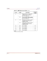
Page 110: ...ule If replacing it perform this procedure on the new module 1 Refer to Table PR7 1 and Figure PR7 1 and set the jumpers as desired filling in the customer settings in Table PR7 1 and Figure PR7 1 NOTE The bold entries in Table PR7 1 and the settings shown in Figure PR7 1 indicate factory settings 5 min Table PR7 1 IIMKM02A Module Jumper Settings1 Jumper Setting Description Customer Setting J1 All...

Page 111: ...les power supply out of toler ance OOT signal to reset the IIMKM02A module 2 3 Enables power supply out of toler ance OOT signal to reset the IIMKM02A module J5 2 3 Do not change 2 3 J6 2 3 Do not change 2 3 J7 2 3 Do not change 2 3 J8 2 3 Do not change 2 3 J9 2 3 Do not change 2 3 NOTE 1 Bold items indicate factory settings Table PR7 1 IIMKM02A Module Jumper Settings1 continued Jumper Setting Des...

Page 112: ...A J6 J9 J8 J7 1 2 3 J2 FACTORY SETTINGS CUSTOM ER SETTINGS J4 J9 J8 J2 J1 J3 J6 J7 J5 1 2 3 1 2 3 1 2 3 1 2 3 1 2 3 1 2 3 3 2 1 J1 FACTORY SETTINGS CUSTOM ER SETTINGS J4 1 2 3 1 2 3 FACTORY SETTINGS CUSTOM ER SETTINGS J3 1 2 3 1 2 3 FACTORY SETTINGS CUSTOM ER SETTINGS ...

Page 113: ...WBPEEUI220771A0 ...

Page 114: ...g with static sensitive devices when performing this procedure Console Model 1 Verify that the main power switch on the PEP is in the off position Check the main power indicator to see if power is removed 2 Figure PR8 1 shows the location of the module in the mul tibus card cage 5 min WARNING 1 There are exposed AC and DC connections inside the cabi net These exposed electrical connections present...

Page 115: ... center of the multibus card cage until they are stopped by the screws 8 Use the bladed screwdriver to tighten the screws on each of the card retainers 9 Install the clear polycarbonate shield onto the front of the multibus card cage All Other Models 1 Verify that the main power switch is in the off position Check the main power indicator to see if power is removed 2 The IIMKM02A module has four r...

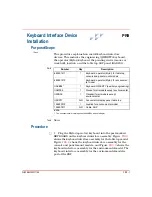
Page 116: ...d interface assembly for the console and panel mount models and Figure PR9 3 shows the keyboard interface assembly for the environmental model The keyboard interface assembly for the environmental model is part of the PEP 10 min Number Qty Description 6638514 1 1 Keyboard operator Mylar for table top console and panel mount models 6638514 2 Keyboard operator Mylar for environmen tal model IIAKB041...

Page 117: ...mental model does not support a mouse or trackball 4 The environmental model supports a joystick Plug the joy stick into the port marked MOUSE PORT on the rear of the CPU Fig PR9 4 Figure PR9 1 Table Top Model Keyboard Interface Assembly Figure PR9 2 Console and Panel Mount Model Keyboard Interface Assembly T01468A KEYBOARD MOUSE TRACKBALL AUX 1 PORT AUX 1 KBD TUNE CONFIG POWER OFF T01447A OFF TUN...

Page 118: ... panel must be assigned an address of two Figure PR9 3 Environmental Model Keyboard Interface Assembly Figure PR9 4 Environmental Model Joystick Connection T01474A KEYB OA RD RELAY ALARM CONTACTS GROUNDING CONDUCTOR E1 CHASSIS GROUND M AIN POW ER O FF TU NE C ON FIG DEGAUSS MAIN PO WER L N L2 WARNING MAY CAUSE SEVERE DAMAGE AIR CONDITIONING ONLY WARNING MAY CAUSE SEVERE DAMAGE SWITCH MUST BET SET ...

Page 119: ... PORT ON KEYBOARD INTERFACE BOARD P1 BACK OF ADP PANEL ADDRESS SWITCH PC BOARD ADDRESS SWITCH SETTINGS SW1 1 2 3 4 5 6 7 8 1 2 3 4 5 6 7 8 1 2 3 4 5 6 7 8 1 2 3 4 5 6 7 8 OPEN OPEN OPEN OPEN SW1 SW1 SW1 ADP 1 ADP 2 ADP 3 ADP 4 P1 SW1 P1 P2 P2 P2 ADP 2 ADP 3 ADP 4 1 2 3 4 5 6 7 8 OPEN ...

Page 120: ...ge can pass through up to two repeaters or network bridges before it reaches its destination Ethernet networks require a terminator at each end of the cable NOTES 1 Be careful using hardware from more than one manufacturer Similar parts can have different specifications that can limit performance 2 This procedure is a general procedure Its intention is to indicate where the cables connect and how ...

Page 121: ...ble entry cutouts to go from component to component Figure PR10 1 Table Top and Console Model Cable Entry Cutouts 197 1 7 76 129 5 5 10 REAR CABLE ENTRY BOTTOM CABLE ENTRY AREA 68 6 2 70 149 4 5 88 DIMENSIONS MILLIMETERS INCHES 63 5 2 50 T01444A ...

Page 122: ...0 PR10 3 Figure PR10 2 Environmental Model Cable Entry Cutout T01472A EYEBOLT REMOVABLE CONDUIT AND CABLE ENTRY AREA FRONT VIEW TOP VIEW 762 0 30 00 1778 0 70 00 777 9 30 63 96 9 3 82 381 0 15 00 DIMENSIONS MILLIMETERS INCHES ...

Page 123: ...WBPEEUI220771A0 ...

Page 124: ...to the printer port on the rear of the CPU or to a DEC server Refer to the Conductor VMS Series 43 Workstation instruction for detailed installation and setup instructions 20 min Number Qty Description 6642555 1 1 Printer cable only if connecting directly to printer port on CPU Table PR11 1 Printers Printer Description CPU Port DEC Server 40790021 Lexmark Color JetPrinter 4079 PLUS 11 in by 17 in ...

Page 125: ...WBPEEUI220771A0 ...

Page 126: ...ermi nals and connecting tables until the monitor bezels are even The leveling screws adjust 26 7 millimeters 1 05 inches 2 Once a unit is secure insert the table support brackets into the cabinet Fig PR12 1 3 Lock the work surfaces into place by pushing the red han dle above the front door to the right until it stops at the bottom of the slot 10 min Number Qty Description 6638625 1 1 Work surface...

Page 127: ... 1 Work Surface Installation T01294A LEFT BRACKET LEFT BUSHING RIGHT BUSHING ADJUSTABLE MOUNTING BOLTS 3 PER BRACKET PIN ONE PER BUSHING TABLE SUPPORT BRACKET RIGHT BRACKET RIGHT BUSHING DIMENSIONS INCHES MILLIMETERS 0 25 6 35 0 25 6 35 0 25 6 35 ...

Page 128: ... associated key board interface assembly Figure PR13 1 shows the panel mount dimensions NOTE Locate the keyboard interface assembly within 1 8 m 6 0 ft of the monitor 2 Use the bladed screwdriver to remove the two cover mount ing screws and remove the top cover 3 Label and disconnect the brightness contrast cable from the monitor 4 Label and disconnect the degauss cable from the degauss switch on ...

Page 129: ...FACE PANEL WITHIN 1 83 M 6 FT OF MONITOR 2 CUTOUT TOLERANCES ARE 0 25 MM 0 01 IN UNLESS OTHERWISE SPECIFIED CUTOUT FOR KEYBOARD INTERFACE PANEL CUTOUT FOR 19 IN PANEL MOUNT 209 6 8 25 6 4 0 25 95 3 3 75 8 7 0 38 228 6 9 00 374 7 14 75 114 3 4 50 457 2 18 00 101 6 4 00 MINIMUM SIDE CLEARANCE BOTH SIDES 472 9 18 62 94 0 3 70 152 4 6 0 76 2 3 00 6 4 4 HOLES 0 250 7 9 6 HOLES 0 312 196 9 MINIMUM TOP C...

Page 130: ...shows the PEP for the console model Figure PR14 3 shows the PEP for the environmental model and Figure PR14 4 shows the PEP for the panel mount model 10 min WARNING 1 There are exposed AC and DC connections inside the cabi net These exposed electrical connections present a shock hazard that can cause injury or death W1 Figure PR14 1 Table Top Model Keyboard Interface Assembly T01469A 2 NC 1 NC 4 N...

Page 131: ...NO 2 NC 1 NC 4 NC 3 NC 6 NC 5 NC 2 COM 1 COM 4 COM 3 COM 6 COM DI 2 DI 1 DO 2 DO 1 DI 2 DI 1 DO 2 DO 1 5 COM L DEGAUS S R E S E T L N L2 NOT USED Figure PR14 3 Environmental Model PEP T01474A KEYB OA RD RELAY ALARM CONTACTS GROUNDING CONDUCTOR E1 CHASSIS GROUND M AIN POW ER O FF TU NE C ON FIG DEGAUSS MAIN PO WER L N L2 WARNING MAY CAUSE SEVERE DAMAGE AIR CONDITIONING ONLY WARNING MAY CAUSE SEVERE...

Page 132: ...the DMM to check each AC outlet to insure that neu tral live and ground are correctly wired and that there are no ground faults 6 Switch the main power switch to the OFF position 7 Use the DMM to verify that there is no power to any of the AC outlets Figure PR14 4 Panel Mount Model PEP T01476A J2 I O PWR ADP PWR FAN PWR CPU INPUT PWR POWER WRIST STRAP PEP INPUT PWR J1 KEYBOARD RESET DEGAUSS ADP 2 ...

Page 133: ...WBPEEUI220771A0 ...

Page 134: ...s disconnect the cables at the distri bution end 3 Make certain the power line cord for he power supply is plugged into the PEP keyboard interface assembly for the table top model 4 Insure that all power wiring is correct 5 Switch the on off switch to the ON position 6 Use the DMM to measure the DC voltages at the multibus card cage backplane for the console model Fig PR15 1 and at P16 on the IIMK...

Page 135: ...operation may result if the power supply voltages are not within tolerance 8 Switch the on off switch to the OFF position 9 Connect all cables removed in Step 2 10 Switch the on off switch to the ON position 11 Use the DMM to check the voltage measurements again 12 Adjust the power supply to obtain the voltage levels to within a tolerance of 0 05 VDC Figure PR15 1 DC Power Test Console Model T0130...

Page 136: ... the monitor Parts None Tools Soft lint free cloth Mild all purpose commercial spray cleaner Procedure 1 Spray the mild all purpose commercial spray cleaner on the soft lint free cloth 2 Use the soft lint free cloth to remove dirt fingerprints or grease from the monitor window and enclosure 5 min ...

Page 137: ...WBPEEUI220771A0 ...

Page 138: ...eral printed circuit board cleaning procedures These procedures cover printed circuit board cleaning and cleaning edge connectors Use the procedures that meet the needs of each printed circuit board Remove all dust dirt oil corrosion or any other contaminant from the printed circuit board 1 hr WARNING 1 Disconnect power before attempting these procedures Fail ure to do so could result in severe or...

Page 139: ...d service vacuum or 1 Spray or wipe the printed circuit board with isopropyl alco hol 99 5 electronic grade 2 Use a foam tipped swab to wipe the printed circuit board 3 When the printed circuit board is clean remove excess sol vent using clean dry filtered compressed air Edge Connector Cleaning General 1 Make a solution of 80 isopropyl alcohol 99 5 electronic grade and 20 distilled water 2 Soak a ...

Page 140: ... only enough force to shine the contact surface Inspect the edge connector after cleaning to assure no loss of contact surface Female Edge Connector Cleaning 1 Soak a soft lint free cloth that is wrapped around the piece of scrap printed circuit board or the foam tipped swab in the 99 5 electronic grade isopropyl alcohol 2 Insert the foam tipped swab or cloth covered printed cir cuit board into th...

Page 141: ...WBPEEUI220771A0 ...

Page 142: ...dures differ depend ing on the keyboard Operator Mylar Keyboard 1 Wipe away dust with the soft lint free cloth 2 Spray the mild all purpose commercial spray cleaner on the soft lint free cloth 3 Clean the dirt and film from the keyboard Engineering QWERTY Keyboard 1 Use the antistatic vacuum to remove dust from the key board 2 Spray the mild all purpose commercial spray cleaner on the soft lint fr...

Page 143: ...WBPEEUI220771A0 ...

Page 144: ...e tightened If the connection is tight the tightening action will verify that it is secure There must not be any motion to loosen the connection 1 Disconnect power from the auxiliary terminal 2 Check and verify that all phase neutral and grounding conductor connections on the PEP are secure 3 Check and verify that the ground nut on the inside of the PEP is secure and tightened to the specified tor...

Page 145: ...WBPEEUI220771A0 ...

Page 146: ...Procedure 1 Remove power from the auxiliary terminal 2 Check the tightness of all power wiring screws within the auxiliary terminal 3 If they are loose use the flat blade torque screwdriver to tighten them to 1 6 Newton meters 14 in lbs 4 Inspect and clean all PEP and DC distribution board connections 1 hr WARNING 1 Disconnect power before attempting these procedures Fail ure to do so could result...

Page 147: ...WBPEEUI220771A0 ...

Page 148: ... indicator to see if power is removed 2 Remove the clear polycarbonate shield that covers the mul tibus card cage 3 Disconnect and label all cables from the multibus card cage 4 Support the front and rear of the multibus card cage while using the Phillips head screwdriver to remove the four screws Fig PR21 1 that secure it to the auxiliary terminal 5 min WARNING 1 Disconnect power before attemptin...

Page 149: ...PR21 2 WBPEEUI220771A0 Procedure 5 Slide the multibus card cage out of the auxiliary terminal Figure PR21 1 Multibus Card Cage Removal T01448A FRONT VIEW SCREWS 4 ...

Page 150: ...long screws around the fan 3 Slide the fan out around the multibus card cage 4 Disconnect the fan power cable 5 Connect the fan power cable to the new fan making sure the red striped conductor is connected to the positive termi nal of the fan 6 Use the bladed screwdriver and four long screws to install the new fan Make sure when installing the new fan that the arrow on the fan points in the direct...

Page 151: ...WBPEEUI220771A0 ...

Page 152: ...er is removed 2 Slide the multibus card cage into the auxiliary terminal 3 Support the front and rear of the multibus card cage while using the Phillips head screwdriver to install the four screws Fig PR23 1 to secure it to the auxiliary terminal 5 min Number Qty Description 6640300 11 1 Multibus card cage NOTE 1 This part not needed if this procedure is part of fan replacement WARNING 1 Disconnec...

Page 153: ...71A0 Procedure 4 Install the clear polycarbonate shield that covers the multi bus card cage 5 Install all cables that were removed from the multibus card cage Figure PR23 1 Multibus Card Cage T01448A FRONT VIEW SCREWS 4 ...

Page 154: ...move the cover from the top of the monitor by using the bladed screwdriver to remove the eight screws and remove the split cover Fig PR24 1 Do not remove the monitor 3 Label and remove all wires and cables from the power supply 4 Carefully tip the monitor and chassis on one side or tip it to the left and support it 5 Use the bladed screwdriver to remove the four screws that hold the power supply t...

Page 155: ...on the PEP 3 Label and remove all wires and cables from the power supply 4 Use the bladed screwdriver to remove the two screws that secure the power supply bracket to the monitor mounting plat form Fig PR24 2 5 There is a metal tab on the bottom of the power supply that sets into a slot on the monitor mounting platform Lift up on Figure PR24 1 Table Top Model Power Supply Removal T01480A COVER MOU...

Page 156: ...before removing the power sup ply Shut down the AC line power plant breaker so that the AC line to the PEP may be disconnected safely 3 Label and remove all wires and cables from the PEP 4 Use the bladed screwdriver to remove the two screws from the PEP end of the bracket supporting the front of the PEP 5 Use the bladed screwdriver to remove the four screws from around the PEP Fig PR24 3 Figure PR...

Page 157: ...ive washers for each standoff 8 Remove the cover from the top of the PEP by using the bladed screwdriver to remove the nine screws Fig PR24 5 9 Disconnect the DC distribution board connector 10 Label and disconnect the wires between the power supply and the incoming AC power 11 Use the bladed screwdriver to remove the four screws that hold the power supply to the center support wall of the PEP Fig...

Page 158: ...in power indicator to see if power is removed Figure PR24 4 Environmental Model IIMKM02A Module Removal Figure PR24 5 Environmental Model Power Supply Removal T01481A IIMKM02A MODULE SCREWS 4 STANDOFFS 4 CONDUCTIVE WASHERS 4 PEP FRONT VIEW T01482A POWER SUPPLY SCREWS 4 PEP FRONT VIEW DC DISTRIBUTION BOARD CONNECTOR COVER SCREWS 9 W1 ...

Page 159: ...r supply mounting screws It is not necessary to remove the monitor Fig PR24 6 3 Label and remove all wires and cables from the power supply 4 Use the bladed screwdriver to remove the four screws that fasten the power supply to the chassis from the outside bottom of the chassis Figure PR24 6 Panel Mount Model Power Supply Removal T01483A SCREWS 4 CHASSIS SCREWS 2 ...

Page 160: ...t the main power switch on the keyboard inter face assembly is in the off position Check the main power indi cator to see if power is removed 2 Carefully tip the monitor and chassis on one side or tip it to the left and support it 10 min Number Qty Description 6638553 51 1 Power supply console model 6640038 1 Power supply table top environmental and panel mount models NOTE 1 This part not needed i...

Page 161: ...plit cover onto the top of the monitor by using the bladed screwdriver to install the eight screws that hold the split cover 6 Set the monitor and chassis back upright Console Model 1 Verify that the main power switch on the PEP is in the off position Check the main power indicator to see if power is removed Figure PR25 1 Table Top Model Power Supply Installation T01480A COVER MOUNTING SCREWS 8 PO...

Page 162: ...t secure the power supply bracket to the monitor mounting plat form Fig PR25 2 4 Install all wires and cables onto the power supply 5 Install the power supply plug into its socket on the PEP Environmental Model 1 Verify that the main power switch on the PEP is in the off position Check the main power indicator to see if power is removed Figure PR25 2 Console Model Power Supply Installation T01400A...

Page 163: ...our screws that secure the IIMKM02A module to the PEP Fig PR25 4 Be sure to install the two nonconductive washers for each standoff 7 Slide the PEP into the front of the cabinet Use caution as the PEP weighs approximately 23 kg 50 lbs 8 Use the bladed screwdriver to install the four screws around the PEP Fig PR25 5 9 Install all wires and cables onto the PEP 10 Use the bladed screwdriver to instal...

Page 164: ...gure PR25 4 Environmental Model IIMKM02A Module Installation Figure PR25 5 Environmental Model PEP Installation T01481A IIMKM02A MODULE SCREWS 4 STANDOFFS 4 CONDUCTIVE WASHERS 4 PEP FRONT VIEW T01484A SCREWS 4 POWER ENTRY PANEL SCREWS 2 ...

Page 165: ...ewdriver to install the four screws that fasten the power supply to the chassis from the outside bottom of the chassis Fig PR25 6 3 Install all wires and cables onto the power supply 4 Install the two chassis screws on the upper edge of the back panel 5 Carefully slide the unit into its operating position W1 Figure PR25 6 Panel Mount Model Power Supply Installation T01483A SCREWS 4 CHASSIS SCREWS ...

Page 166: ...The table top model does not have a PEP Console Model 1 Verify that the main power on the PEP is in the off position Check the power indicator to see if power is removed 2 Verify that the AC line power plant circuit breaker to the auxiliary terminal is shut down so that the AC line can be safely disconnected 20 min Number Qty Description 6638353 7 1 PEP console model 6639503 5 PEP environmental mo...

Page 167: ...al 8 Slide the new PEP into the front of the auxiliary terminal 9 Align the five holes around the outside of the PEP with the mounting holes in the auxiliary terminal frame Figure PR26 1 Console Model PEP T01471A U DEGAUSS REAR VIEW NOTICE CONNECT POWER CORD BEFORE CONNECTING SIGNAL CABLE 2 NO POW ER MAIN P OWER ON OFF WARNING AVE RTISSE MENT 120 240V PERIPHE RA L POWE R UPPER CRT POWER SUPPLY LOW...

Page 168: ... Connect the remaining cables to the front of the PEP Environmental Model 1 Verify that the main power on the PEP is in the off position Check the power indicator to see if power is removed 2 Verify that the AC line power plant circuit breaker to the auxiliary terminal is shut down so that the AC line can be safely disconnected 3 Label and remove all cables from the front of the PEP Fig PR26 3 Fig...

Page 169: ...AY ALARM CONTACTS GROUNDING CONDUCTOR E1 CHASSIS GROUND M AIN POW ER O FF TU NE C ON FIG DEGAUSS MAIN PO WER L N L2 WARNING MAY CAUSE SEVERE DAMAGE AIR CONDITIONING ONLY WARNING MAY CAUSE SEVERE DAMAGE SWITCH MUST BET SET FOR PROPER VOLTAGE AUX 1 PORT AUX KBD WRIST STRAP 120 240 VAC CRT 120 240 LIGHT 120 V TERMINAL 120 240 A C 120 V MOUSE TRACKBALL GROUNDED NEUTRAL CONDUCTOR CURRENT CARRYING CONDU...

Page 170: ...rify that the AC line power plant circuit breaker to the auxiliary terminal is shut down so that the AC line can be safely disconnected 3 Label and remove all cables from the front of the PEP Fig PR26 5 4 There are two screws accessible from the rear of the panel in which the auxiliary terminal is mounted that secure the PEP and mounting tray Use the bladed screwdriver to remove the two screws Fig...

Page 171: ...he rear of the panel 7 Use the bladed screwdriver to install the two screws that hold the PEP and mounting tray to the panel 8 Connect all wires and cables to the PEP Figure PR26 6 Panel Mount Model PEP Replacement T01485A POWER ENTRY PANEL REMOVE 2 SCREWS FROM REAR OF PANEL CPU ...

Page 172: ...abel all cables from the CPU 3 Remove the two screws that secure the mounting plate to the track on each side of the cabinet Fig PR27 1 4 Slide the CPU and mounting plate completely out of the rear of the cabinet 5 Place the CPU and mounting plate on a clean surface 6 Remove the four screws that secure the CPU to the mount ing plate 10 min Number Qty Description 6642485 1 1 CPU Tektronix model XP4...

Page 173: ...he CPU to the mounting plate 9 Slide the CPU and mounting plate all the way into the cabinet 10 Install the two screws that secure the mounting plate to the rails on each side of the cabinet 11 Install all cables onto the CPU Figure PR27 1 Table Top Model CPU Replacement T01487A CPU REAR VIEW DOORS REMOVED SCREWS 2 ...

Page 174: ... the support bracket 5 Slide the CPU and mounting plate out of the rear of the auxiliary terminal 6 Remove the four screws that hold the CPU to the mounting plate 7 Install the four screws to secure the new CPU to the mounting plate 8 Slide the new CPU and mounting plate into the rear of the auxiliary terminal 9 Install the two screws that hold the rear of the mounting plate to the support bracket...

Page 175: ...m the CPU 3 Remove the four retaining screws that fasten the mounting plate to the shelf Fig PR27 3 4 Carefully slide the CPU and mounting plate out of the cabinet 5 Remove the four screws that hold the CPU to the mounting plate 6 Install the four screws to secure the new CPU to the mounting plate 7 Carefully slide the CPU and mounting plate into the cabinet W1 Figure PR27 3 Environmental Model CP...

Page 176: ...ff position Check the power indicator to see if power is removed 2 Remove and label all cables from the CPU 3 Remove the two screws that hold the CPU to the support bracket Fig PR27 4 4 Slide the CPU out along the support bracket 5 Slide the new CPU in along the support bracket 6 Install the two screws to secure the CPU to the support bracket W1 Figure PR27 4 Panel Mount Model CPU Removal T01489A ...

Page 177: ...PR27 6 WBPEEUI220771A0 Procedure 7 Install all cables onto the CPU ...

Page 178: ...for the table top model Figure PR28 2 shows the keyboard interface assembly for the console and panel mount models and Figure PR28 3 shows the keyboard interface assembly for the envi ronmental model The keyboard interface assembly for the environmental model is part of the PEP 2 Unplug the QWERTY engineering keyboard from the port marked AUX KBD on the keyboard interface assembly 3 Unplug the poi...

Page 179: ...FF TUNE CONFIG KEYBOARD AUX 1 PORT MOUSE TRACKBALL AUX KBD Figure PR28 3 Environmental Model Keyboard Interface Assembly T01474A KEYB OA RD RELAY ALARM CONTACTS GROUNDING CONDUCTOR E1 CHASSIS GROUND M AIN POW ER O FF TU NE C ON FIG DEGAUSS MAIN PO WER L N L2 WARNING MAY CAUSE SEVERE DAMAGE AIR CONDITIONING ONLY WARNING MAY CAUSE SEVERE DAMAGE SWITCH MUST BET SET FOR PROPER VOLTAGE AUX 1 PORT AUX K...

Page 180: ...ocedure WBPEEUI220771A0 PR28 3 Figure PR28 4 Environmental Model Joystick Connection T01490A KEYBOARD PORT MOUSE PORT PORT 1 PORT 0 VIDEO PORT ETHERNET NETWORK CABLE AUX OUT AC IN 1 0 ON OFF POWER SWITCH ...

Page 181: ...WBPEEUI220771A0 ...

Page 182: ... PR29 1 3 If it is necessary to remove the bezel remove the four screws that secure the bezel to the auxiliary terminal Fig PR29 2 4 Remove the ADP panel from the auxiliary terminal or from the bezel if the bezel was removed 5 Label and disconnect the cables 6 Verify that SW1 on the new ADP panel is set as shown in Figure PR29 1 7 Connect the cables 8 Install the ADP panel into the bezel 10 min Nu...

Page 183: ...e bezel 10 If the bezel was removed from the auxiliary terminal install it and use the bladed screwdriver to install the four screws Figure PR29 1 IIADP02 Replacement T01303A BACK OF ADP PANEL BEZEL SCREWS 2 ADDRESS SWITCH PC BOARD SW1 TO MKM BOARD 26 PIN P2 P4 P1 POWER IN CABLE 8 7 6 5 OPEN 4 3 2 1 ...

Page 184: ...Procedure WBPEEUI220771A0 PR29 3 Figure PR29 2 IIADP02 Bezel Removal T01401A REAR VIEW SCREWS 4 ADP ...

Page 185: ...WBPEEUI220771A0 ...

Page 186: ...the sealing ring to the cabinet Fig PR30 1 4 Use the bladed screwdriver to remove the four screws that secure the ADP panel to the cabinet and remove it 5 Verify that SW1 on the new ADP panel is set as shown in Figure PR30 2 6 Install the ADP panel into the cabinet 7 Use the bladed screwdriver to install the four screws 8 Install the sealing ring and use the bladed screwdriver to install the ten s...

Page 187: ...anel Figure PR30 1 NADS03 Replacement T01486A SCREWS 10 Figure PR30 2 NADS03 Switch Settings T01477A ANNUNCIATOR DISPLAY PANEL ADP ADDRESS SWITCH SETTINGS TO MKM BOARD 26 PIN P2 P1 COM N C 5 PIN 1 POWER IN CABLE ADP 1 SW1 BACK OF ADP PANEL ADDRESS SWITCH SW1 PC BOARD P3 ...

Page 188: ...or The environmental model has the keyboard interface assembly on the front of the power entry panel behind the front door The panel mount model has the key board interface assembly below the monitor and above the CPU 1 Be sure to set the switches as shown in Figure PR31 1 when replacing the keyboard interface assembly 10 min Number Qty Description 6638554 2 1 Keyboard interface assembly console e...

Page 189: ...2 BLU RED YEL 5V GND 12V 12V SW1 F2 F1 F3 J1 P3 KEYBOARD AUX 1 PORT AUX KBD MOUSE TRACKBALL P4 P5 P6 P2 P8 ASSY 6638238 1 SW1 SWITCHES 5 6 AND 7 ARE CLOSED ON TP P3 ON DC DISTRIBUTION BOARD F1 F2 AND F3 ARE 2 A 250 V FAST BLOW TO P7 ON MKM BOARD AND TO P2 ON ADP BOARD P9 NOT USED P10 TO MOUSE PORT ON CPU CAUTION SWITCHES 5 6 AND 7 ARE CLOSED ON SWITCHES 1 THROUGH 4 AND 8 ARE OPEN OFF IF THEY ARE N...

Page 190: ...ront cover 4 Disconnect the power cord connectors from the fans mounted in the rear cover 5 Remove the rear cover 6 If the monitor has a touchscreen disconnect the touch screen cable at the connector between the monitor and the IIMKM02A module 10 min WARNING 1 There are exposed AC and DC connections inside the cabi net These exposed electrical connections present a shock hazard that can cause inju...

Page 191: ... old VGA cable and care fully pull the old VGA cable down through the monitor mount ing tube support NOTE It may be necessary to cut several tie wraps that hold the old VGA cable to the auxiliary terminal To make access easier remove the front support bracket for the fan shroud assembly by removing the four mounting screws 11 Detach the new VGA cable from the old VGA cable and fin ish removing the...

Page 192: ...the off position Check the power indicator to see if power is removed 2 Remove the power cord and RGB cables from the rear of the monitor Secure the RGB cables out of the way 3 If the monitor has a touchscreen disconnect the touch screen cable from the IIMKM02A module 10 min WARNING 1 There are exposed AC and DC connections inside the cabi net These exposed electrical connections present a shock h...

Page 193: ...the bolts and washers on each side of the monitor mounting tray at the rear of the monitor These bolts attach the monitor mounting tray to the auxiliary terminal shelf 8 Slide the monitor out of the rear of the auxiliary terminal 9 Place the monitor and tray onto a solid flat surface 10 Protect the monitor screen and set the screen on the pro tective surface 11 Use the bladed screwdriver to remove...

Page 194: ...the PEP is in the off position Check the power indicator to see if power is removed 2 Remove the bezel 3 Remove the power cord and RGB cables from the rear of the monitor Secure the RGB cables out of the way 4 If the monitor has a touchscreen disconnect the touch screen cable from the IIMKM02A module 5 Slide the monitor out of the panel W2 W1 W2 ...

Page 195: ...WBPEEUI220771A0 ...

Page 196: ...I220771A0 PR34 1 PR34 Touchscreen Removal Purpose Scope This procedure explains how remove the touchscreen Parts None Tools None Procedure 1 Firmly pull on the touchscreen to release it from the monitor 1 min ...

Page 197: ...WBPEEUI220771A0 ...

Page 198: ... edge of the hook tape with the inner edge of the touchscreen border 3 Apply the shorter pieces along the inside side edges of the touchscreen butting one end of each against the edge of the long piece and align them with the inner edge of the touch screen border 4 Trim off the excess hook tape 5 Cut the loop tape into three pieces one slightly longer than the top edge of the monitor face and two ...

Page 199: ...ply the shorter pieces along the side edges of the monitor tube butting the edges against the edge of the long piece 8 Trim off the excess loop tape 9 Apply a strip of vinyl tape or equivalent along the bottom edge of the tube face to dust seal the gap between the touch screen and the tube face 10 Position the touchscreen on the monitor face so that the hook tape and loop tape meet and hold ...

Page 200: ...nitor to its mounting plate 4 Attach the RGB cables Fig PR36 1 10 min Number Qty Description 1948623 91 1 Monitor 19 in NOTE 1 This part is not needed if this procedure is part of touchscreen replacement WARNING 1 There are exposed AC and DC connections inside the cabi net These exposed electrical connections present a shock hazard that can cause injury or death 2 The monitor will slide out by its...

Page 201: ... the rear cover 9 Install the front cover using the front cover mounting screws 10 If a touchscreen is installed on the monitor refer to the Operation Conductor VMS and Configuration Conductor VMS instructions to perform an on line calibration of the touchscreen Figure PR36 1 Monitor Connections and Adjustments T01507A COMPOSITE SYNCH RESISTOR POSITION RESISTOR SW ITCHES FOR 75 TERM INATION Ω NO R...

Page 202: ...fy that the main power on the PEP is in the off position Check the power indicator to see if power is removed 10 min Number Qty Description 1948623 91 1 Monitor 19 in NOTE 1 This part is not needed if this procedure is part of touchscreen replacement WARNING 1 There are exposed AC and DC connections inside the cabi net These exposed electrical connections present a shock hazard that can cause inju...

Page 203: ... the monitor refer to the Operation Conductor VMS and Configuration Conductor VMS instructions to perform an on line calibration of the touchscreen Console Model 1 Verify that the main power on the PEP is in the off position Check the power indicator to see if power is removed W2 Figure PR37 1 Monitor Connections and Adjustments T01507A COMPOSITE SYNCH RESISTOR POSITION RESISTOR SW ITCHES FOR 75 T...

Page 204: ... to the auxiliary terminal shelf 9 If the monitor has a touchscreen connect the touchscreen cable to the IIMKM02A module 10 Install the power cord and RGB cables to the rear of the monitor Fig PR37 1 11 Verify that the SYNC switch on the rear of the monitor is set to the GRN position and the resistor switches are set to the resistor position 12 If a touchscreen is installed on the monitor refer to...

Page 205: ...fy that the main power on the PEP is in the off position Check the power indicator to see if power is removed 2 Slide the monitor into the panel 3 Install the bezel 4 If the monitor has a touchscreen connect the touchscreen cable to the IIMKM02A module 5 Install the power cord and RGB cables to the rear of the monitor Fig PR37 1 6 Verify that the SYNC switch on the rear of the monitor is set to th...

Page 206: ... to remove the four screws that secure the touchscreen controller card to the IIMKM02A module 3 Verify that the jumpers and switches on the new touch screen controller card are set as shown in Figure PR38 1 4 Mount the touchscreen controller card so that P14 and P15 on the touchscreen controller card mate with P14 and P15 on the IIMKM02A module 5 Insert the four nylon spacers between the touchscre...

Page 207: ...eration Conductor VMS and Configura tion Conductor VMS instructions to perform an on line cali bration of the touchscreen Figure PR38 1 Touchscreen Controller Card Installation T01479A P14 W 3 W 4 W 2 W 1 P15 P14 P15 CO NNECTOR PINS PLUG INTO M KM BOARD FACTORY SET DO N OT CHANG E TO SERIAL PORT 1 ON C PU TO UCH SCREEN CABLE M OUNT ING HO LES 4 W 1 INSTALLED W 2 N OT INSTALLED R3 1 5 S1 S2 S1 8 7 ...

Page 208: ...model Console Model Front and Rear Doors 1 Insert the tabs on the door into the holes in the auxiliary panel frame 2 Push up and in on the doors to install them 3 Insert the key into the lock and turn it turn clockwise Top Cover 1 Install the top cover so the five holes in the top cover align with the holes in the auxiliary terminal frame 2 Use the inch Allen wrench to install the five Allen screw...

Page 209: ...PR39 2 WBPEEUI220771A0 Procedure 2 Pull in on the handle of each end latch 3 Turn each end latch turn 4 Use the inch Allen wrench to turn the middle latch on the door to be closed turn 1 8 ...

Page 210: ...op model 1 2 Dimension drawings A 1 Dipswitches 3 2 E Environmental model 1 4 Ethernet wiring PR10 1 F Factory cabling B 1 Fan replacement PR22 1 Functional operation 2 1 G Grounding 3 6 H How to use this instruction 1 7 I IIADP01 Installation PR9 1 Removal PR28 1 IIADP02 replacement PR29 1 IICPI0 installation PR4 1 IICPI01 installation PR4 1 IIMKM02A Repair PR7 1 Setup PR7 1 Inspection 3 2 Instal...

Page 211: ...ng connections PR19 1 Keyboard cleaning PR18 1 Monitor cleaning PR16 1 PEP checking and inspection PR20 1 Printed circuit board cleaning PR17 1 Schedule 5 2 Module Installation PR8 1 Removal PR6 1 Monitor Cleaning PR16 1 Installation PR36 1 PR37 1 Removal PR32 1 PR33 1 Mouse Installation PR9 1 Removal PR28 1 Multibus card cage Installation PR23 1 Removal PR21 1 Mylar keyboard cleaning PR18 1 N NAD...

Page 212: ...R28 1 Upper monitor PR32 1 PR36 1 Repair and replacement 6 1 S Safety considerations 3 3 Software installation 3 6 Spare parts 7 1 Special handling 3 1 Dipswitches 3 2 Specifications 1 8 Static sensitive devices 3 1 T Table top model 1 2 Touchscreen Installation PR35 1 Removal PR34 1 Touchscreen controller card replacement PR38 1 Trackball Installation PR9 1 Removal PR28 1 Troubleshooting 4 1 AC p...

Page 213: ...WBPEEUI220771A0 ...

Page 214: ...or process automation For the location nearest you please contact the appropriate regional office AMERICAS 29801 Euclid Avenue Wickliffe Ohio USA 44092 Telephone 1 216 585 8500 Telefax 1 216 585 8756 ASIA PACIFIC 152 Beach Road Gateway East 20 04 Singapore 189721 Telephone 65 391 0800 Telefax 65 292 9011 EUROPE AFRICA MIDDLE EAST Via Puccini 2 16154 Genoa Italy Telephone 39 10 6582 943 Telefax 39 ...

Reviews: