vi
15 August 1994
I-E96-117B1
No.
Title
Page
List of Figures
®
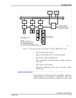
1-1.
Example Analog Control Station within the INFI 90 Hierarchy ............................... 1-3
2-1.
SAC Station Application Example .......................................................................... 2-2
2-2.
Flow Diagram of SAC Station Operation from Power Up to Normal Operation ......... 2-5
2-3.
SAC Station Normal Operating Modes .................................................................... 2-8
2-4.
Basic Station Configuration ................................................................................. 2-10
2-5.
Module Configuration with Cascade Set Point from External Source .................... 2-11
2-6.
Ratio Station Configuration ................................................................................. 2-12
2-7.
Block Diagram of SAC Station Circuitry ............................................................... 2-13
2-8.
Station Bypass Circuitry...................................................................................... 2-15
2-9.
Electric Drive Circuit ........................................................................................... 2-17
2-10.
Analog Output Circuitry ...................................................................................... 2-18
3-1.
Dipswitch and Jumper Locations on the SAC Station Circuit Board ....................... 3-2
3-2.
Station Housing Panel Cutout and Mounting Dimensions .................................... 3-12
3-3.
Cable Connections for Two Analog Control Stations on One
TCS Termination Unit.......................................................................................... 3-16
3-4.
Cable Connections for TCS Termination Unit with Multiple Interconnected
SAC Stations ....................................................................................................... 3-17
3-5.
Cable Connections for the NTRL03 Termination Unit ........................................... 3-18
3-6.
Cable Connections for the NIRL03 Termination Module ....................................... 3-19
3-7.
Cable Connections for the ICS Termination Module with One Station,
No Bypass ........................................................................................................... 3-20
3-8.
Cable Connections for the ICS and IDS Modules with Interconnected Stations
and Bypass ......................................................................................................... 3-21
4-1.
SAC Faceplate ....................................................................................................... 4-1
5-1.
Error Code E01 Troubleshooting Flowchart ........................................................... 5-5
5-2.
Error Codes E03, E04, E05 and E06 Troubleshooting Flowchart ............................ 5-6
5-3.
Error Codes E07 and E08 Troubleshooting Flowchart ............................................ 5-7
5-4.
Error Code E17 Troubleshooting Flowchart ........................................................... 5-8
5-5.
Error Code E18 Troubleshooting Flowchart ........................................................... 5-9
5-6.
Error Code E19 Troubleshooting Flowchart ......................................................... 5-10
5-7.
Error Code E20 Troubleshooting Flowchart ......................................................... 5-11
5-8.
Troubleshooting Flowchart for General Operational Failures ................................ 5-13
A-1.
NTCS04 Terminal Assignments.............................................................................. A-2
B-1.
NICS01 Terminal Assignments ..............................................................................B-1
C-1.
NIDS01 Terminal Assignments ..............................................................................C-1


