background image

DESCRIPTION AND OPERATION

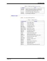
MODES OF OPERATION

2 - 12


I-E96-117B

®

Ratio Station

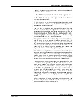
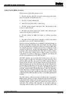
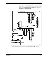
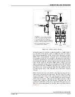
A variable controlled by another process variable determines
the set point for a ratio station. The MFP module calculates the
set point by multiplying the wild variable by a ratio index set in
function code 80. The operator can change the ratio index
through the set raise/lower pushbutton. By changing the ratio
index, the operator changes the set point ratio that the control
algorithm uses to calculate the set point. When the SAC station
transfers to manual operation from automatic ratio operation,
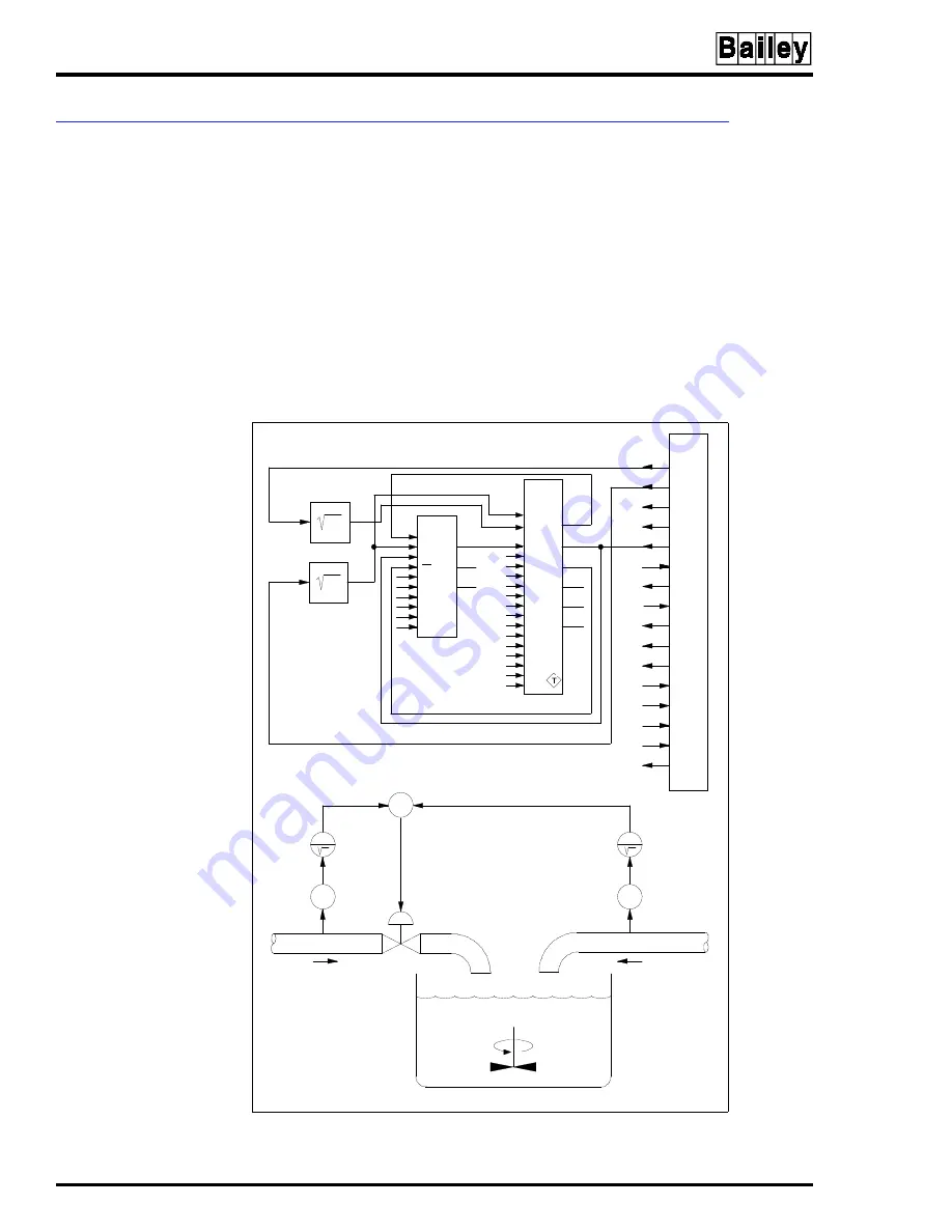
it goes into manual basic operation. Figure

2-6

 shows an

example ratio station.

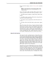
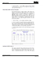
While in ratio mode, the bar graph indicates the value of the
set point while the alphanumeric indicates the ratio index. The

Figure 2-6.  Ratio Station Configuration

WILD VARIABLE

CONTROLLED VARIABLE

(156)
80

(7)
70

(7)
60

S2

S7

S9

S8

S6

S1

S1

S1

S5

S4

S3

S10

APID

BD

CO

BI

SP

FF

N/A

N/A

R

PV

TF

TR

DI

II

(80)

(79)

120

121

122

123

124

125

126

127

128

129

101

100

102

103

104

105

S1

S2

S3

S24

S29

S28

S27

S26

S25

S4

S22

S21

S20

S19

S18

S5

S30

M/A

MFC/P

SP

O

C-F

C

C/R

A

PV

AI1

DI2

DO4

DO3

DO2

DO1

DI3

DI1

AI2

AO2

AO2

AO1

AO1

AI4

AI3

ST

SP

A

HAA

TRS2

AO

LDA

HDA

LAA

TR

CX

LX

C/R

AX

MI

TS

TRPV

CISI/O

T00291A

CONTROLLED VARIABLE

UNCONTROLLED (WILD) VARIABLE

BLEND TANK

FC

FY

FY

FT

FT

0

SP

PV

Summary of Contents for infi 90 IISAC01

Page 1: ...Process Control and Automation Solutions from Elsag Bailey Group E96 117 Analog Control Station IISAC01...

Page 2: ...UIPEMENTS LECTRONIQUES SONT SENSIBLES AUX PERTURBATIONS PAR FR QUENCE RADIO DES PR CAUTIONS DEVRONT TRE PRISES LORS DE L UTILISATION DU MAT RIEL DE COMMUNICATION PORTATIF LA PRUDENCE EXIGE QUE LES PR...

Page 3: ...so provides analog output backup in the event of other system faults This instruction explains the station features specifications and operation It includes installation procedures and explains how to...

Page 4: ...hrough 4 9 Original 5 1 through 5 2 Original 5 3 31 August 1994 5 4 through 5 13 Original 6 1 through 6 4 Original 7 1 through 7 2 Original 8 1 Original A 1 through A 2 Original B 1 Original C 1 Origi...

Page 5: ...vicing Special Handling This module uses electrostatic sensitive devices SPECIFIC WARNING Wear eye protection whenever working with cleaning solvents When removing solvents from printed circuit boards...

Page 6: ...rant l entretien Precautions de Manutention Ce module contient des composantes sensibles aux d charges lectrostatiques AVERTISSEMENT D ORDRE SP CIFIQUE Portez toujours des lunettes de protection lorsq...

Page 7: ...Level 2 9 Computer Level 2 9 Basic Station 2 9 Cascade Station 2 10 Ratio Station 2 12 SAC STATION I O CIRCUITRY 2 13 Bypass Circuitry 2 14 Electric Drive Circuitry 2 16 Analog Output Circuitry 2 18 A...

Page 8: ...emoving the Analog Control Station 3 23 FUNCTION CODE CONFIGURATION 3 23 SECTION 4 OPERATING PROCEDURES 4 1 INTRODUCTION 4 1 FACEPLATE OPERATION 4 1 Alphanumeric Display 4 1 Annunciators 4 4 Bar Graph...

Page 9: ...ipswitch SW2 Positions 1 through 3 3 5 3 4 SAC Station Jumper Settings 3 6 3 5 Dipswitch SW3 Positions 1 through 3 3 7 3 6 Dipswitch SW4 Position 1 3 8 3 7 Dipswitch SW4 Positions 2 through 8 3 9 3 8...

Page 10: ...Termination Unit 3 16 3 4 Cable Connections for TCS Termination Unit with Multiple Interconnected SAC Stations 3 17 3 5 Cable Connections for the NTRL03 Termination Unit 3 18 3 6 Cable Connections fo...

Page 11: ...tem engineers and technicians must read this instruction before installing and operating the SAC station Refer to the Table of Contents to find specific information HARDWARE DESCRIPTION The SAC statio...

Page 12: ...hows an example of SAC stations within the INFI 90 hierarchy 1 Other modules include the IMMFC03 IMMFC04 and IMMFC05 Multi Function Controller Modules the IMCOM03 and IMCOM04 Controller Modules and th...

Page 13: ...nance information Read and understand this document before placing the analog control Figure 1 1 Example Analog Control Station within the INFI 90 Hierarchy TO OTHER STATIONS 32 STATIONS MAX PER COMMU...

Page 14: ...res Maintenance Contains a table of scheduled maintenance procedures Repair Replacement Procedures Explains how to repair and replace the SAC station Support Services Explains the services and trainin...

Page 15: ...on when it is in bypass operation Manual Override An operator initiated mode which has similar functionality as bypass mode This mode is entered independently of the state of the primary module and CI...

Page 16: ...umber Title I E92 500 3 CBC01 Batch Command Controller I E92 500 7 CLC03 04 Loop Command Controller I E96 116 NDIS01 Digital Indicator Station I E96 200 Function Code Application Manual I E96 201 IMMF...

Page 17: ...er cable CKS002 CBC controller cable IISAC01 Analog control station IMCIS02 Control I O slave module IMCOM03 04 Controller modules IMMFC03 04 05 Multi function controller IMMFP01 02 03 Multi function...

Page 18: ...aphs 200 segments for process variable and set point at 0 5 resolution 100 segments for output at 1 0 resolution 8 character 14 segment alphanumeric display Bypass Automatic entry or selected from fac...

Page 19: ...radio frequency interference Values are not available at this time Do not use communication equip ment any closer than 2 meters from the station panel Ambient temperature 0 to 70 C 32 to 158 F Humidit...

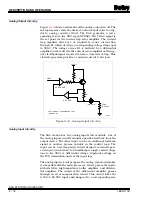
Page 20: ...CIS module communicates to the MFP module through the I O expander bus The SAC station receives and sends information from and to the MFP module through the termination devices Figure 2 1 shows an exa...

Page 21: ...and other operating parameters The SAC station pro vides the operator interface This interface includes Bar graphs Pushbuttons Annunciators Alphanumeric displays Figure 2 1 SAC Station Application Exa...

Page 22: ...exists In manual override the station deci phers the MFP module update message but ignores any request to transfer to any other operating mode The station can only be forced to exit manual override by...

Page 23: ...s station opera tion In return the station sends control output in manual operation set point in manual or automatic operation and pushbutton information to the MFP module The MFP module can force the...

Page 24: ...NORM MAN GOOD COMMUNICATION CIS STATUS GOOD PREVIOUS MODE NORM AUTO GOOD COMMUNICATION CIS STATUS GOOD PREVIOUS MODE NORM CASC RATIO NORM MAN BAD COMMUNICATION AND AUTO BYPASS DISABLED BAD COMMUNICAT...

Page 25: ...t the operator can monitor the electric drive position or current output through the analog inputs For manual override the operator can target the demand output of the SAC station to the control outpu...

Page 26: ...ns raise lower contacts pushbuttons The output raise lower contacts on the faceplate energize the drive raise or lower relay circuitry Manual Override Operation The manual override operational mode is...

Page 27: ...scade ratio station Figure 2 3 shows a diagram of SAC station normal operating modes When the station loses communication with the MFP module it defaults to either the stand alone mode or bypass mode...

Page 28: ...tation variables are controlled by the external station interface The station function code function code 80 operates a com puter watchdog timer that must be started by the supervisory computer progra...

Page 29: ...oint adjustment from the station faceplate Cascade station operates only in the automatic local and automatic computer Figure 2 4 Basic Station Configuration TANK T00289A FT LC SP S2 S1 S2 S3 S4 S30 S...

Page 30: ...S9 S8 S7 S5 S1 S4 S3 S10 S1 S2 S3 S24 S29 S28 S27 S26 S25 S4 S22 S21 S20 S19 S18 S5 S30 S2 S7 S9 S8 S6 S1 S5 S4 S3 S10 S3 101 80 AI1 DI2 DO4 DO3 DO2 DO1 DI3 DI1 AI2 AO2 AO2 AO1 AO1 AI4 AI3 ST S24 S29...

Page 31: ...operation it goes into manual basic operation Figure 2 6 shows an example ratio station While in ratio mode the bar graph indicates the value of the set point while the alphanumeric indicates the rat...

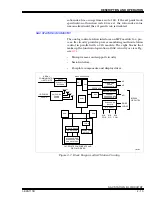
Page 32: ...tion of SAC circuitry are see Fig ure 2 7 Microprocessor and support circuitry Serial interface Faceplate components and display driver Figure 2 7 Block Diagram of SAC Station Circuitry DAC TRANSMITTE...

Page 33: ...ay use this information to update displays or send to the MFP module in a station update message The bypass circuit is a microprocessor controlled four to 20 milliamp analog output that provides analo...

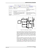
Page 34: ...to the load see Figure 2 8 During normal operation the bypass nor mally high BYPASS N H signal is a logic one which turns Q1 Table 2 1 Bypass Circuit Functions and Specifications Function Purpose Spe...

Page 35: ...on is in electric drive mode For more information on display options refer to Section 3 Figure 2 9 shows the electric drive circuit The electric drive circuit is powered from the terminal block connec...

Page 36: ...n the SAC station exits electric drive bypass manual over ride mode to normal mode operation the new value for control output will be the value of the analog input as defined in the column of Tables 3...

Page 37: ...he SAC station has two analog inputs AI available One of the analog inputs usually monitors position feedback from the output device The other input can be an additional feedback signal or another pro...

Page 38: ...to five VDC signal to a digital value Analog input two has a square root display option When enabled dipswitch SW4 position one it takes the square root of the zero to 100 percent input signal This si...

Page 39: ...in the static shielding bag until you are ready to install them in the system Save the bag for future use 2 Ground Bag Before Opening Before opening a bag con taining an assembly with semiconductors...

Page 40: ...packing material and container to store the hardware 5 Store the hardware in an environment of good air quality free from temperature and moisture extremes SELECTING OPTIONS There are four dipswitches...

Page 41: ...elect the communication rate five or 40 kilobaud for the RS 485 communication port that matches the commu nication rate of the module The baud rate of the controller module and MFC module are fixed at...

Page 42: ...e 3 2 for examples of address settings 2 Select an address in applications having multiple SAC sta tions each station must have a different address SAC sta tions using the 5 kilobaud serial communicat...

Page 43: ...ion 2 settings 3 Set dipswitch SW2 position 2 for reverse or normal demand output and record the dipswitch setting in the space provided in Table 3 3 Electric Drive Option SW2 Position 3 and JP2 This...

Page 44: ...ware revi sion B 3 or higher have these options DISPLAY OPTIONS The SAC station has three distinct display operating modes stand alone bypass manual override and normal The AI1 and AI2 designators sho...

Page 45: ...record the dipswitch settings in the space provided in Table 3 5 Square Root Enable SW4 Position 1 This option enables the square root function on the second analog input AI2 With this option enabled...

Page 46: ...f the options selected 3 Set SW4 positions 2 through 4 to the positions that enable the desired display options and record the dipswitch settings in the space provided in Table 3 7 Bypass Manual Overr...

Page 47: ...PV SP AI12 PV SP CO 0 1 0 PV SP Blank PV SP CO 0 1 1 PV SP All on PV SP CO 1 0 0 AI23 SP CO PV SP CO 1 0 1 AI23 SP AI12 PV SP CO 1 1 0 AI23 SP Blank PV SP CO 1 1 1 AI23 SP All on PV SP CO Manual overr...

Page 48: ...higher To set the electric drive mode display option 1 Determine the electric drive mode display options required for your application 2 Refer to Tables 3 5 3 6 and 3 7 for the required stand alone o...

Page 49: ...1 See Figure 3 2 for the station housing panel cutout and mounting dimensions Prepare the panel opening accordingly 2 Insert the housing through the panel opening until the front flange is in contact...

Page 50: ...ABLE MOUNTING ANGLE OF FRONT PLATE IS 0 TO 75 FROM VERTICAL 4 STANDARD ENVIRONMENTAL SPECIFICATIONS FOR THE SYSTEMS ARE APPLICABLE 66 0 2 60 138 0 1 0 5 43 0 04 144 0 5 67 25 4 1 00 2 54 0 10 TYP MIN...

Page 51: ...ctor NKCL01 and NKCL11 NKTL01 cable N type plug NKTL01 N type plug 3 000 0 10 000 0 NKCS01 and NKCS11 TCS termination unit P2 or P3 SAC station P1 137 16 450 00 TRL termination unit P3 Refer to Tables...

Page 52: ...unit P1 61 0 200 0 Primary MFP module P3 TMP termination unit P2 Redundant MFP module P3 TMP termination unit P1 NKTU02 and NKTU12 MFP or CIS module P3 IMP or ICS termination module P1 61 0 200 0 R204...

Page 53: ...it handling a single or double station setup 1 Connect the wiring from the electric drive analog output and analog inputs to the termination unit Refer to Appendix A for terminal assignments 2 Connect...

Page 54: ...he NTRL03 Termination Unit Figure 3 5 shows the cable connections for the NTRL03 termi nation unit For more information refer to the NTRL02 and NTRL03 Fiber Optic Remote Link and Electrical Remote Lin...

Page 55: ...M or KTU cable connector in the TMU backplane cable from termination module to the module 5 The ICS termination module can terminate up to 4 SAC stations without bypass Figure 3 7 shows a cable diagra...

Page 56: ...01 11 NKLM01 11 NKPL01 11 NKLM01 11 NO ANALOG OUTPUT BYPASS CAPABILITY NO ANALOG OUTPUT BYPASS CAPABILITY NO ANALOG OUTPUT BYPASS CAPABILITY ANALOG OUTPUT BYPASS CAPABILITY NKDS03 13 NKCS02 12 NKDS02...

Page 57: ...L01 02 NKPL03 04 NKTL01 NIRL03 SERIAL LINK WIRE NICS01 NIDS01 NKTU02 12 RIBBON CABLE 6634408A2 NKTD01 11 NKDS01 11 NKTD02 12 NKTD02 NKID12 NKTD02 NKID12 ANALOG OUTPUT BYPASS CAPABILITY NO ANALOG OUTPU...

Page 58: ...01 and NKTM11 or NKTU02 cable connector in the TMU backplane cable from termination module to the module 6 Figure 3 8 shows a termination module and single station with bypass and interconnection conf...

Page 59: ...cable NOTE Only 1 analog input is available to the bypass station when using the NICS01 NIDS01 termination module pair Figure 3 8 Cable Connections for the ICS and IDS Modules with Interconnected Stat...

Page 60: ...itry Before inserting the station in its housing verify that 1 The termination cable is properly connected to the termina tion unit and to the correct slot of the station housing 2 All station operati...

Page 61: ...station from the housing 3 Grasp the station faceplate from the top and bottom at the left edge and pull the station to disconnect it from its cable connection and remove it from the housing FUNCTION...

Page 62: ...ion faceplate with membrane pushbuttons manual override switch annuncia tors bar graphs and alphanumeric display Alphanumeric Display The alphanumeric display is an eight digit display Each digit disp...

Page 63: ...or error and alarm codes and their meanings For more information refer to Section 5 Table 4 1 Special Characters on the Alphanumeric Display Character Meaning Three horizontal lines in the leftmost di...

Page 64: ...s condition does not disrupt station operation It warns the operator that the process variable is below a predetermined limit E13 Alarm Process Variable PV High Occurs when the process variable rises...

Page 65: ...on See Figure 2 2 for a flow diagram of the SAC station operation Manual Override Switch The manual override switch forces the control system into open loop control The operator has direct control of...

Page 66: ...ratio Transfers operation from automatic basic cascade or ratio to manual basic The LED inside the pushbutton is on when the station is in the manual mode of operation Raises or lowers the control ou...

Page 67: ...the cause of the SAC station entering bypass is an open load and the load is reconnected before using the M A switch Under these conditions toggling the M A switch removes the control loop from bypas...

Page 68: ...on is in stand alone mode the operator can place the station in manual override if the station is a bypass station JP1 has pins one and two jumpered and the manual override switch is enabled To place...

Page 69: ...he OUT raise lower pushbutton and sends that value to the CIS mod ule The adjustment of set point has no effect on the process until it is in auto mode NOTE Enabling control output or set point tracki...

Page 70: ...raise lower pushbutton If the station is in the bypass operational mode because of a communication failure it will return to normal operation when module to station communi cation is established If a...

Page 71: ...d point to prevent damage to the station circuit by electrostatic discharge ERROR CODES NOTE Always secure control of the loop through another source before disconnecting the station if a failure occu...

Page 72: ...dule product instruction for informa tion about module status LEDs and corrective action Bad function code configuration Check function code 80 configuration within the module Insure baud rate of stat...

Page 73: ...n related corrective action E16 Membrane pushbutton fault User pressing mul tiple pushbuttons Keypad is OK Cycle through the alarm list to clear out the E16 error E16 generated without user interventi...

Page 74: ...rong display options selected with electric drive option enabled Refer to Section 3 for display option information 1 Check the stand alone display options and verify that they are set correctly for op...

Page 75: ...CHECK MFP TO TU TM CABLE CONNECTION CHECK MFP LEDs FOR MODULE STATUS MFP LEDs ARE NORMAL DONE REFER TO THE MFP INSTRUCTION FOR CORRECTIVE ACTION NO YES YES NO DONE ERROR CODE REMAINS NO YES REPLACE T...

Page 76: ...OLTAGE WITHIN SPEC REPLACE STATION YES NO YES NO YES NO DONE REPLACE TU TM REPLACE STATION CABLE IS VOLTAGE WITHIN SPEC YES NO CONTACT BAILEY CONTROLS VERIFY AI DIPSHUNT SETTING VERIFY CORRECT OPERATI...

Page 77: ...BYPASS MANUAL OVERRIDE MANUAL STAND ALONE PHYSICALLY SECURE PROCESS IS TU TM SET FOR CURRENT OUTPUT YES NO SET TU INSERT STATION REPLACE STATION YES NO REMOVE ASSOCIATED IMCIS02 YES NO REPLACE IMCIS02...

Page 78: ...e 5 4 Error Code E17 Troubleshooting Flowchart SECURE CONTROL OF LOOP THROUGH SOME OTHER SOURCE RESET STATION REPLACE STATION STATION IN BYPASS OR MANUAL OVERRIDE ERROR CODE REMAINS ERROR CODE E17 ON...

Page 79: ...5 9 Figure 5 5 Error Code E18 Troubleshooting Flowchart REMOVE STATION INSERT STATION JUMPER PINS 1 AND 2 ON JP3 REPLACE STATION PINS 1 AND 2 JUMPERED ON JP3 ERROR CODE REMAINS ERROR CODE E18 ON ALPH...

Page 80: ...lowchart CHECK STAND ALONE DISPLAY OPTIONS AND SET FOR USE WITH ELECTRIC DRIVES CHECK BYPASS MANUAL OVERRIDE DISPLAY OPTIONS AND SET FOR USE WITH ELECTRIC DRIVES REPLACE STATION ERROR CODE REMAINS DIS...

Page 81: ...ng Flowchart PLACE M A SWITCH IN A POSITION REMOVE STATION REPLACE STATION SEAT P5 CONNECTOR ON STATION ERROR CODE REMAINS P5 SEATED PROPERLY ON STATION ERROR CODE REMAINS M A SWITCH IN CORRECT POSITI...

Page 82: ...24 VDC wiring to the termination device 1 Use a digital voltmeter to verify that there is 24 VDC on the termination device Measure the voltage across the terminal E2 and common E1 2 If there is no po...

Page 83: ...CE THE STATION YELLOW MANUAL LED REMAINS ON STATION WILL NOT EXIT BYPASS SECURE CONTROL OF PROCESS THROUGH ANOTHER SOURCE REPAIR OPEN PROCESS LOOP RESET THE STATION DONE NO NO BARGRAPHS FLICKER OR DIM...

Page 84: ...have experience working with process control systems and know what precautions to take when working on live AC systems PREVENTIVE MAINTENANCE SCHEDULE Table 6 1 is the preventive maintenance schedule...

Page 85: ...ic grade Natural bristle brush PREVENTIVE MAINTENANCE PROCEDURES This section covers tasks from Table 6 1 preventive mainte nance schedule that require specific instruction or further explanation The...

Page 86: ...or an antistatic field service vac uum cleaner Another method of washing the printed circuit board is 1 Clean the printed circuit board by spraying or wiping the board with a foam tipped swab wetted...

Page 87: ...or and work it back and forth to clean the contacts 3 Rinse the edge connector contacts by spraying with isopro pyl alcohol 4 Remove excess alcohol and dry using compressed air Checking Connections Ch...

Page 88: ...power The station in stand alone or normal mode can be removed from a system under power 2 Use a straight blade screwdriver to turn the captive screw located behind the legend door and release the st...

Page 89: ...the station faceplate at the left edge and pull the sta tion from its housing 3 Remove F1 from the fuse holder see Figure 3 1 for the location of F1 4 Replace F1 by installing a 1 0 A 250 V fuse Baile...

Page 90: ...r and reference used in identify ing the part When ordering standard parts from Bailey Con trols Company use the part number and description from the replacement parts section of the manual Parts not...

Page 91: ...s per termination unit can have bypass All other dipshunt settings on the NTCS04 termina tion unit relate to the IMCIS02 Control I O Slave Module Refer to the IMCIS02 Control I O Slave Module product...

Page 92: ...1 AI2 P2 1 AI3 XU3 AI1 P2 1 AI2 XU2 AI2 P3 1 TB3 COMMON 24 VDC DI3 XU7 DO4 DO3 TB2 DI2 XU6 DI1 XU5 DO2 DO1 TB1 RAISE 1 R L COMMON 1 LOWER 1 M A POWER 1 M A SELECT 1 M A COMMON 1 AI ANALOG INPUT AO ANA...

Page 93: ...the station when using the ICS termination module For bypass and analog input capability the NIDS01 Station Termination Module and the ICS termina tion module are required NOTE Terminating one or two...

Page 94: ...ion with the NICS01 Controller Station Termination Module provides bypass capability and an electric drive termination for SAC sta tions For more information on the IDS termination module refer to the...

Page 95: ...enable 3 7 Stand alone mode 3 7 E Error codes 4 2 5 1 Corrective action 5 2 E01 5 2 5 5 E02 5 2 E03 5 2 5 6 E04 5 2 5 6 E05 5 2 5 6 E06 5 2 5 6 E07 5 2 5 3 5 7 E08 5 3 5 7 E10 5 3 E11 5 3 E12 5 3 E13...

Page 96: ...ocedures 7 1 Replacement parts 8 1 Required tools and equipment 6 2 S SAC station I O circuitry 2 13 Analog input 2 18 Analog output 2 18 Bypass circuitry 2 14 Electric drive 2 16 Scheduled maintenanc...

Page 97: ...756 ASIA PACIFIC 152 Beach Road Gateway East 20 04 Singapore 189721 Telephone 65 391 0800 Telefax 65 292 9011 EUROPE AFRICA MIDDLE EAST Via Puccini 2 16154 Genoa Italy Telephone 39 10 6582 943 Telefax...

Reviews: