DESCRIPTION AND OPERATION
SAC STATION I/O CIRCUITRY
2 - 16
I-E96-117B
®
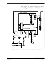
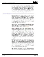
on, reverse biasing D1 and turns Q2 and Q3 off. Q1 sinks the
SAC station output to ground and the CIS module output
drives the load through D2 and D3. In bypass or manual over-
ride, the BYPASS N.H. signal is a logic zero. This state causes
Q1 to turn off while Q2 and Q3 turn on. D1 is now forward
biased, allowing the SAC station to source the output current
to R
L
. With Q3 on, the R2/R3 voltage divider reverse biases D3
which disconnects the CIS analog output from the load.
Electric Drive Circuitry
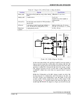
The electric drive circuit provides both relay contact outputs
and transfer signal (M/A_SELECT) to both universal and RW
electric drives. Dipswitch SW2 position three enables this
option, and the position of jumper JP2 determines drive selec-
tion. This circuit is operational only in stand-alone, bypass and
manual override modes of operation. Terminal blocks one and
four of the NTCS04 termination unit and terminal block one of
the NIDS01 Station Termination Module contain all the field
wiring for the drives (refer to Table
).
There are three stand-alone mode display options and three
bypass mode display options that determine how the display
operates when the station is in electric drive mode. For more
information on display options refer to
.
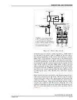
Figure
shows the electric drive circuit. The electric drive
circuit is powered from the terminal block connected by either
the system I/O supply or an external power source (24 VDC).
The power supply designator at the termination units and ter-
mination modules are M/A_PWR and M/A_COM. Providing
power supply inputs independent from the I/O supply allows
the electric drive circuit to be powered from a secured source. If
the I/O supply fails, the relay K1 de-energizes. This connects
the M/A_PWR and M/A_COM inputs across the series circuit
of the raise/lower faceplate membrane switches and relays.
Pressing the membrane switches causes the electric drive to
change positions.
The SAC station microcontroller and interlocking relay contacts
control the electric drive circuit operation. Upon application of
power, the station goes through an initialization cycle. During
initialization the microcontroller deciphers the user selectable
options. During the initialization cycle, the microprocessor will
not assert any control signals. With transistor Q1 turned off,
relay K1 is de-energized. This causes the M/A_SELECT signal
to be asserted and allows the raise/lower relays to be controlled
by the raise/lower membrane pushbuttons.
The sense of the M/A_SELECT signal is determined by jumper
JP2. In stand-alone mode the microprocessor takes control of


