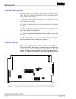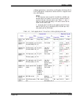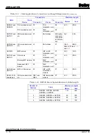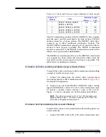
INSTALLATION
SELECTING OPTIONS
3 - 4
I-E96-117B
®
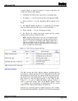
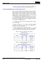
2. Refer to Table
and set SW1, position 2 for the desired
communication rate and record the dipswitch setting in the
space provided in Table
Station Address (SW1, Positions 3 through 8)
Each station must have a unique address. A SAC station (con-
figured for 40 kilobaud communication rate) can have any
address from zero to 63 when supported by an IMMFP01 or
IMMFP02 module revision C.0 firmware or higher or an
IMMFP03 module. All other modules (COM, QRC, MFC and
MFP modules with revision A or B firmware) can support up to
eight stations at five-kilobaud communication rate. Use
addresses zero to seven when using these modules. To set the
SAC station address:
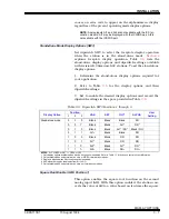
1. Refer to Table
for examples of address settings.
2. Select an address (in applications having multiple SAC sta-
tions, each station must have a different address). SAC sta-
tions using the 5-kilobaud serial communication link must use
addresses 0 through 7. Stations using the 40-kilobaud serial
communication link can use any address from 0 to 63.
3. Set the station address and record it in the space provided
in Table
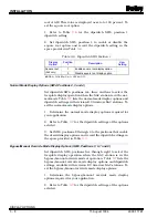
Auto Bypass (SW2, Position 1)
This option setting determines what mode of operation the sta-
tion will transfer to if a communication failure occurs. Auto
bypass automatically places the station in the bypass mode
when a communication failure occurs. With auto bypass
Table 3-2. Dipswitch SW1 Address Positions 3 through 8
Address
Example
Dipswitch Position
(Binary Value)
3
(32)
4
(16)
5
(8)
6
(4)
7
(2)
8
(1)
0
0
0
0
0
0
0
16
0
1
0
0
0
0
32
1
0
0
0
0
0
48
1
1
0
0
0
0
63
1
1
1
1
1
1
User Settings
NOTE: 0 = CLOSED or ON, 1 = OPEN or OFF.


