INSTALLATION
DISPLAY OPTIONS
3 - 6
I-E96-117B
®
control output in manual override or bypass operation. To
enable the electric drive option:
1. Determine the drive type required for your application.
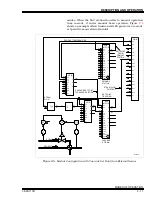
2. See Figure
for the location of JP2 and dipswitch SW2.
3. Refer to Table
for the dipswitch SW2, position 3 set-
tings.
4. Set dipswitch SW2, position 3 to enable the electric drive
and record the setting in the space provided in Table
5. Refer to Table
for the JP2 jumper setting.
6. Set JP2 for the electric drive type and record the jumper
setting in the space provided in Table
.
NOTE: Dipswitch SW2, position 3 must be in the disable position
when using the standard analog output in bypass operation (refer to
Table
). There are 3 stand-alone mode display options and 3
bypass mode display options available when using the electric drive
option. Only IISAC01 Analog Control Stations that are firmware revi-
sion B.3 or higher have these options.
DISPLAY OPTIONS
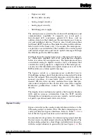
The SAC station has three distinct display operating modes:
stand-alone, bypass/manual override and normal. The AI1 and
AI2 designators should not be confused with the physical ana-
log input to the termination device. Each operating mode dis-
play option is selected independently of the other modes.
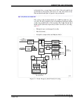
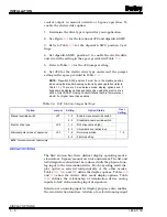
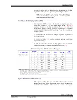
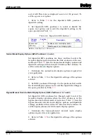
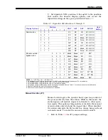
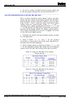
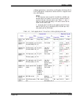
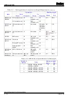
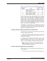
Tables
, and
define the display options. Tables
and
show the electric drive mode display options. Table
defines the relationship of termination device analog
inputs to SAC station analog input designators.
Selection of an analog input for display purposes also enables
the error detection function. A failure of a selected analog input
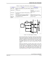
Table 3-4. SAC Station Jumper Settings
Option
Jumper
Setting
Option Status
User
Setting
Manual override switch
JP1
1 - 2
Enable manual override switch
2 - 3
Disable manual override switch
Electric drive type
JP2
1 - 2
RW drive (active high)
2 - 3
Universal drive (active low)
Microcomputer mode of operation
JP3
1 - 2
Normal operation
1 - 2
2 - 3
Factory setting
NOTE: Shaded area denotes default setting.

