INSTALLATION
DISPLAY OPTIONS
3 - 8
I-E96-117B
®
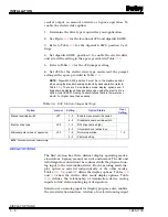
root of AI2. This value is displayed as zero to 100 percent. To
set the square root option:
1. Refer to Table
for the dipswitch SW4, position 1
dipswitch setting.
2. Set dipswitch SW4, position 1 to enable or disable the
square root option and record the dipswitch setting in the
space provided in Table
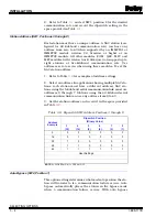
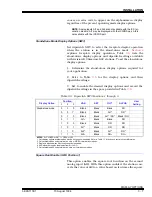
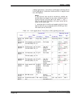
Normal Mode Display Options (SW4, Positions 2, 3 and 4)
Set dipswitch SW4, positions two, three and four to select the
faceplate display operation when the SAC station is in the nor-
mal mode. Table
lists the normal mode display options and
dipswitch settings with revision B.3 firmware SAC stations. To
set the normal mode display options:
1. Determine the normal mode display options required for
your application.
2. Refer to Table
for the dipswitch settings of the options
selected.
3. Set SW4, positions 2 through 4 to the positions that enable
the desired display options and record the dipswitch settings in
the space provided in Table
.
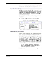
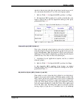
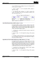
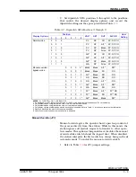
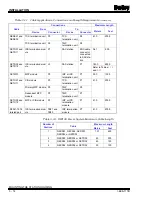
Bypass/Manual Override Mode Display Options (SW4, Positions 5, 6, 7 and 8)
Set dipswitch SW4, positions five through eight to select the
faceplate display operation when the SAC station is in the
bypass/manual override mode of operation. Table
lists the
bypass/manual override mode display options and dipswitch
settings available with revision B.3 firmware SAC stations. To
set the bypass/manual override mode display options:
1. Determine the bypass/manual override mode display
options required for your application.
2. Refer to Table
for the dipswitch settings of the options
selected.
Table 3-6. Dipswitch SW4 Position 1
Display
Option
Position
1
Description
User
Setting
Square root
(AI2 only)
1
Enable square root display option
0
Disable square root display option
NOTE: 0 = CLOSED or ON, 1 = OPEN or OFF.
15 August 1994
I-E96-117B1

