INSTALLATION
ELECTRIC DRIVE MODE DISPLAY OPTIONS (SW3 AND SW4)
3 - 10
I-E96-117B
®
2. Set JP1 to enable or disable manual override switch and
record the jumper setting in the space provided in Table
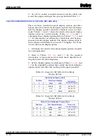
ELECTRIC DRIVE MODE DISPLAY OPTIONS (SW3 AND SW4)
There are three stand-alone mode display options and three
bypass/manual override mode display options that determine
how the display operates when the station is in electric drive
mode. Tables
and
show the electric drive mode display
options action on control outputs. Tables
, and
summarize those display options. Refer to Tables
,
, and
for information on setting the stand-alone and bypass/
manual override display options. The display options apply to
SAC stations with firmware revision B.3 or higher. To set the
electric drive mode display option:
1. Determine the electric drive mode display options required
for your application.
2. Refer to Tables
, and
for the required
stand-alone or bypass/manual override mode dipswitch set-
ting that select the desired options.
3. Set the display options by referring to Tables
, and
for the dipswitch position that enable the desired display
options and record the switch setting in the space provided.
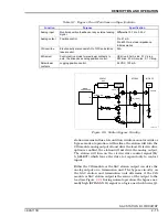
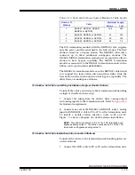
Table 3-8. Dipswitch SW3 Electric Drive Mode
Display Options
Stand-Alone Display Mode
Position
Bar Graph Display
Action On
Control Output
1
2
3
VAR
OUT
0
0
1
Blank
AI1
AI1 to CO
1
1
0
AI2
AI1
AI1 to CO
1
1
1
AI2
Blank
AI2 to CO
Table 3-9. Dipswitch SW4 Electric Drive Mode
Display Options
Manual Override/Bypass Display Mode
Position
Bar Graph Display
Action On
Control Output
5
6
7
8
VAR
OUT
0
0
0
0
Blank
AI1
AI1 to CO
0
1
0
1
AI2
AI1
AI1 to CO
1
0
0
1
AI2
Blank
AI2 to CO
15 August 1994
I-E96-117B1

