INSTALLATION
MOUNTING THE STATION HOUSING
I-E96-117B
3 - 15
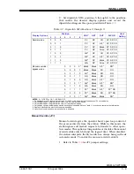
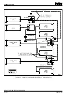
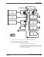
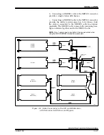
The ICS termination module with the NKTD02 cable supplies
only the power and the serial link to the SAC station. The SAC
station cannot be a bypass station. The NKDS03 cable inter-
connects up to three additional nonbypass stations. The
NICS01/NIDS01 termination module pair is required to allow a
station to have bypass capability. The NICS01 termination
module is connected to the NIDS01 termination module with a
ribbon cable (part number 6634408A2).
The NIDS01 termination module uses the NKTD01 cable which
can support two four-station interconnection links. Only the
first station in the interconnection has bypass capability. The
other three are nonbypass stations.
Termination Unit Cable and Wiring Installation (Single or Double Station)
To install the cables and wires to the termination unit handling
a single or double station setup:
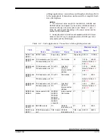
1. Connect the wiring from the electric drive, analog output
and analog inputs to the termination unit. Refer to
for terminal assignments.
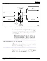
2. Connect one end of the NKCS01 or NKDS01 (only 1 analog
input with NKDS01) cable to P2 or P3 on the termination unit.
To install a double station, install a cable in P2 and P3.
Figure
shows a diagram of a double station installation.
NOTE: The station connected to P2 of the TCS termination unit
bypasses analog output 1. The station connected to P3 of the TCS
termination unit bypasses analog output 2.
Termination Unit Cable Installation (Interconnected Stations)
To install the cables to the termination unit handling intercon-
nected stations:
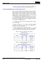
1. Connect the KCS cable to P2 or P3 on the termination unit.
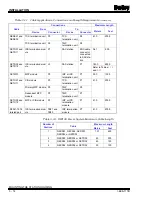
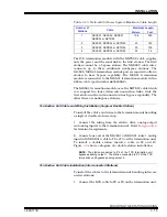
Table 3-13. Network 90 Power System Maximum Cable Length
Number of
Stations
Cable
Maximum Length
Meters
Feet
1
NKCS01, NKCS02, NKDS01,
NKDS02 or NKTD02
106
350
2
NKCS02, NKDS02 or NKTD02
45
150
3
NKCS02, NKDS02 or NKTD02
30
100
4
NKCS02, NKDS02 or NKTD02
22
75

