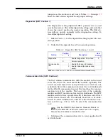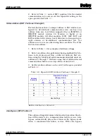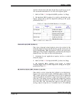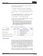
INSTALLATION
MOUNTING THE STATION HOUSING
I-E96-117B
3 - 17
Termination Module Cable Installation (without Bypass)
To install the termination module without bypass:
1. Partially remove the termination module from the termina-
tion mounting unit (TMU) leaving the terminals next to the
faceplate exposed.
2. Connect one end of the KDS cable to J2 of the ICS termina-
tion module. Connect the other end of the cable to the rear of
the station housing for the analog control station.
3. Connect twisted pair serial link wiring between NIMP01
and NICS01 modules. Take care not to cross A and B serial
channels.
4. Push the termination module into the TMU unit until it
seats in the KTM or KTU cable connector in the TMU backplane
(cable from termination module to the module).
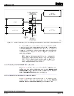
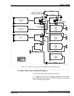
5. The ICS termination module can terminate up to 4 SAC
stations without bypass. Figure
shows a cable diagram of
one station terminated on the ICS termination module.
NOTE: No analog inputs are available for display purposes in the
SAC station when using an NICS01 termination module.
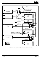
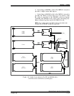
Figure 3-4. Cable Connections for TCS Termination Unit with Multiple Interconnected SAC Stations
IMCIS02
IMMFP01/02/03
P1
P1
P3
P3
P2
P2
NKTU01/11
NKTU01/11
NKTU01/11
NKSE01/11
T00299A
NKSE01/11
NKSE01/11
NKDS03/13
NKDS03/13
NKDS02/12
NKCS02/12
TO REDUNDANT
MFP IF REQUIRED
TO SECOND
GROUP OF UP
TO 32 STATIONS
TO ADDITIONAL NTCS04
AS REQUIRED
TO NEXT STATION
(4 STATIONS MAX)
P2
P2
P3
P1
P1
P7
P5
P5
P4
P6
P4
P3
NTMP01
NTCS04
IISAC01
(WITH BYPASS)
IISAC01
(NO BYPASS)
IISAC01
(NO BYPASS)
P1
P1
P1

