I-E96-117B1
15 August 1994
v
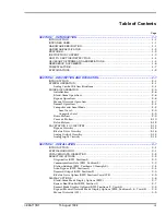
Table of Contents
(continued)
Page
SECTION 8 - SUPPORT SERVICES ...........................................................................................8-1
INTRODUCTION ...........................................................................................................8-1
REPLACEMENT PARTS AND ORDERING INFORMATION ..............................................8-1
TRAINING ....................................................................................................................8-1
TECHNICAL DOCUMENTATION ...................................................................................8-1
APPENDIX A - NTCS04 CONTROLLER/STATION TERMINATION UNIT................................ A-1
INTRODUCTION .......................................................................................................... A-1
APPENDIX B - NICS01 CONTROLLER/STATION TERMINATION MODULE.......................... B-1
INTRODUCTION .......................................................................................................... B-1
APPENDIX C - NIDS01 STATION TERMINATION MODULE.................................................... C-1
INTRODUCTION .......................................................................................................... C-1
List of Tables
No.
Title
Page
1-1.
Glossary of Terms and Abbreviations .....................................................................1-5
1-2.
Reference Documents ............................................................................................1-6
1-3.
Nomenclature ........................................................................................................1-7
1-4.
IISAC01 Analog Control Station Specifications .......................................................1-8
2-1.
Bypass Circuit Functions and Specifications ........................................................2-15
3-1.
Dipswitch SW1 Positions 1 and 2 ...........................................................................3-3
3-2.
Dipswitch SW1 Address Positions 3 through 8 .......................................................3-4
3-3.
Dipswitch SW2 Positions 1 through 3 ....................................................................3-5
3-4.
SAC Station Jumper Settings .................................................................................3-6
3-5.
Dipswitch SW3 Positions 1 through 3 ....................................................................3-7
3-6.
Dipswitch SW4 Position 1 ......................................................................................3-8
3-7.
Dipswitch SW4 Positions 2 through 8 ....................................................................3-9
3-8.
Dipswitch SW3 Electric Drive Mode Display Options ............................................3-10
3-9.
Dipswitch SW4 Electric Drive Mode Display Options ............................................3-10
3-10.
Termination Device and SAC Station Designator Relationship ..............................3-12
3-11.
Cable Applications, Connections and Length Requirements ..................................3-13
3-12.
INFI 90 Power System Maximum Cable Length .....................................................3-14
3-13.
Network 90 Power System Maximum Cable Length ..............................................3-15
4-1.
Special Characters on the Alphanumeric Display ...................................................4-2
4-2.
Analog Control Station Error Codes and Alarms .....................................................4-2
4-3.
Annunciators .........................................................................................................4-4
4-4.
Membrane Pushbutton Operation ..........................................................................4-5
5-1.
Corrective Action for SAC Error Codes ....................................................................5-2
5-2.
Troubleshooting General Failures.........................................................................5-12
6-1.
Preventive Maintenance Schedule ..........................................................................6-2
7-1.
Recommended Spare Parts List ..............................................................................7-1
A-1.
NTCS04 Termination Unit Dipshunt Configuration ............................................... A-1


