DESCRIPTION AND OPERATION
SAC STATION I/O CIRCUITRY
I-E96-117B
2 - 15
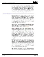
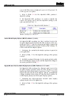
station remains in this state until forced into manual override or
bypass mode of operation. At this time, the station will turn the
CIS module analog output off and drive the load. If electric drive
option is enabled, the station will not drive the analog output.
The station will turn on the electric drive control signal (M/
A_SELECT) which forces the drive to respond only to contact
inputs.
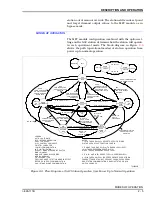
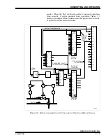
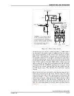
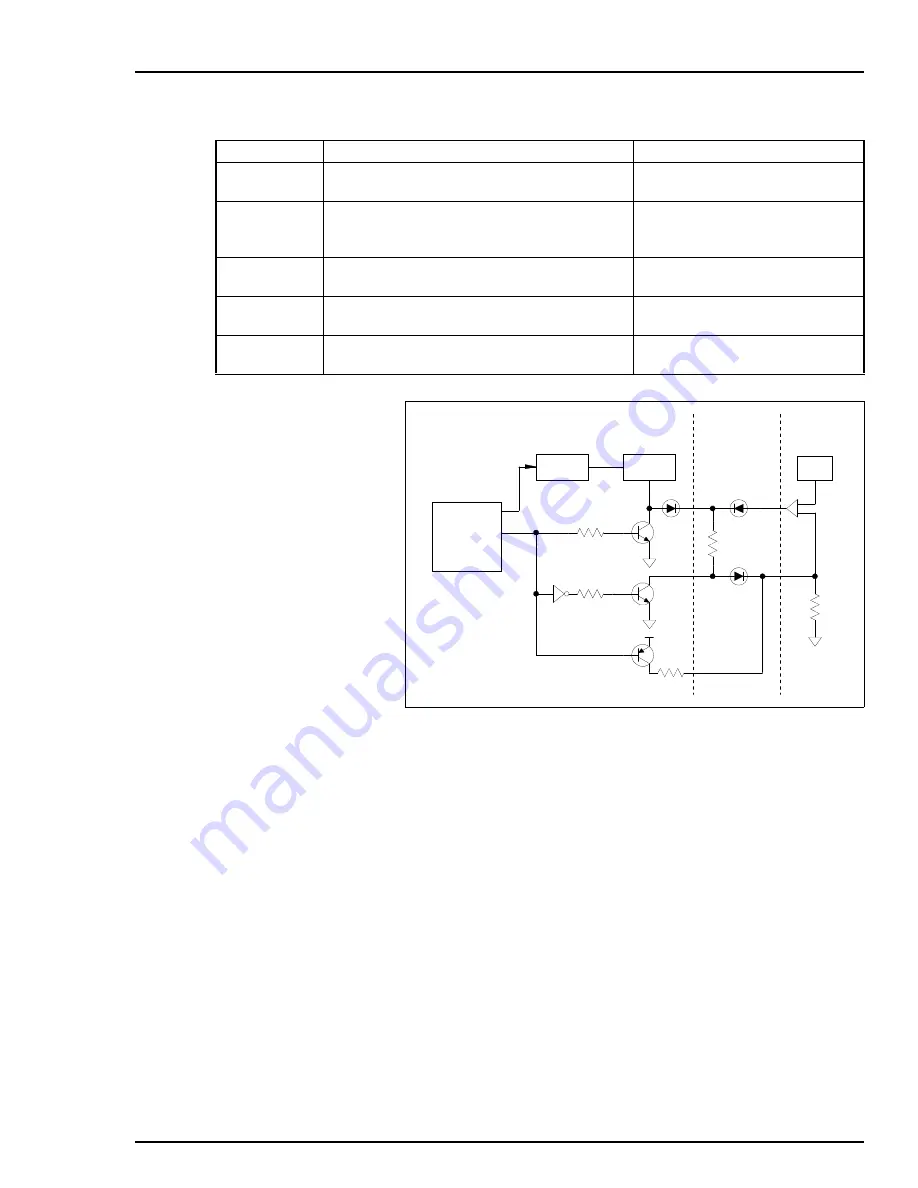
Either the CIS module or the SAC station output can drive the
analog output on a termination unit. The bypass circuitry on
the SAC station and termination unit determine if the CIS
module or SAC station output is the source of the output to the
load (see Figure
). During normal operation, the bypass nor-
mally high (BYPASS N.H.) signal is a logic one which turns Q1
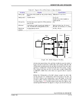
Table 2-1. Bypass Circuit Functions and Specifications
Function
Purpose
Specification
Analog input
Monitors position feedback or any external analog
signal.
Differential: 0.75 to 5.25 V
Analog output
Position control.
3 to 21 mA
0 to 600
Ω
max load impedance
8-bit resolution
CIS override
Electronically disconnects AO of CIS and station
takes control.
N/A
M/A select
Controls drive mode to raise/lower contacts. In
auto, the drive uses analog position control.
UE drive: 40 mA sink, 0.1 V drop
RW drive: 40 mA source, 0.1 V drop
Raise/lower
contacts
Jogging position control.
24 VDC, 100 mA
Figure 2-8. Station Bypass Circuitry
T 0 02 9 3A
MICRO-
PROCESSOR
BYPASS N.H.
I/O
OUT
4-20 mA
R3
Q3
Q2
Q1
R2
D3
D2
D1
OVERRIDE CIS
4-20 mA
R (LOAD)
L
DAC
CURRENT
AMPLIFIER
D/A
IISAC01
NTCS04
IMCIS02

