INSTALLATION
SELECTING OPTIONS
I-E96-117B
3 - 5
disabled, the station enters the stand-alone mode upon a mod-
ule communication failure. To set the auto bypass option:
1. Refer to Table
for dipswitch SW2, position 1 settings.
2. Set dipswitch SW2, position 1 to enable or disable the auto
bypass option and record the dipswitch setting in the space
provided in Table
Demand Output (SW2, Position 2)
The reverse demand output option reverses the current of the
demand output in bypass mode (low bar graph at zero percent
equals 20 milliamps, high bar graph at 100 percent equals four
milliamps). The module configuration performs this function in
normal mode. To set the reverse demand output:
1. Determine if your application requires reverse or normal
demand output.
2. Refer to Table
for dipswitch SW2, position 2 settings.
3. Set dipswitch SW2, position 2 for reverse or normal
demand output and record the dipswitch setting in the space
provided in Table
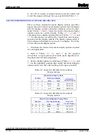
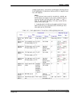
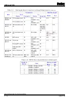
Electric Drive Option (SW2, Position 3 and JP2)
This option is active when the SAC station is in stand-alone,
bypass or manual override mode. With this option enabled, the
SAC station asserts the signal M/A select at the termination
unit forcing the electric drive to accept raise/lower contact out-
puts only. This option requires setting one dipswitch position
and one jumper position to enable the electric drive option and
select the drive type. Disabling this option causes the station
analog output to operate as a standard four to 20-milliamp
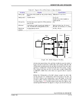
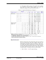
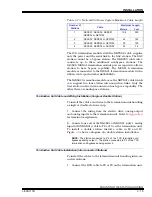
Table 3-3. Dipswitch SW2 Positions 1 through 3
Option
Position
Description
User
Setting
1
2
3
Auto bypass
1
Enable auto bypass
0
Disable auto bypass
Demand output
1
Reverse demand output
0
Normal demand output
Electric drive
1
Enable electric drive
0
Disable electric drive
NOTE: 0 = CLOSED or ON, 1 = OPEN or OFF.


