INSTALLATION
DISPLAY OPTIONS
I-E96-117B
3 - 7
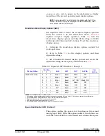
causes an error code to appear on the alphanumeric display
regardless of the present operating mode display options.
NOTE: Analog inputs AI1 and AI2 are not available with the ICS ter-
mination module. AI1 may be displayed with the ICS/IDS pair. AI2 is
not available with the ICS/IDS pair.
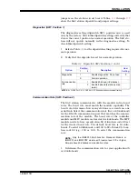
Stand-Alone Mode Display Options (SW3)
Set dipswitch SW3 to select the faceplate display operation
when the station is in the stand-alone mode.
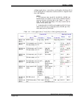
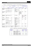
explains faceplate display operation. Table
lists the
stand-alone display options and dipswitch settings available
with revision B.3 firmware SAC stations. To set the stand-alone
display options:
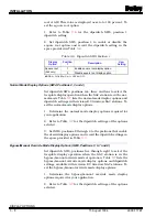
1. Determine the stand-alone display options required for
your application.
2. Refer to Table
for the display options and their
dipswitch settings.
3. Set to enable the desired display options and record the
dipswitch settings in the space provided in Table
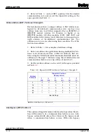
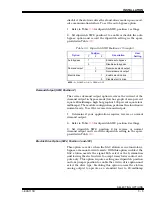
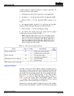
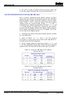
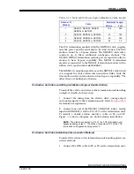
Square Root Enable (SW4, Position 1)
This option enables the square root function on the second
analog input (AI2). With this option enabled, the station con-
verts the value of AI2 to a value based on ten times the square
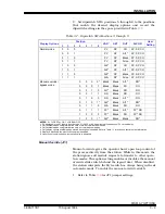
Table 3-5. Dipswitch SW3 Positions 1 through 3
Display Option
Position
VAR
SET
OUT
ALPHA
User
Setting
1
2
3
Stand-alone mode
0
0
0
Blank
Blank
Blank
DO
0
0
1
1
Blank
Blank
AI1
2
DO
3
0
1
0
Blank
Blank
AI1
2
/ DO
4
Blank / DO
0
1
1
AI1
2
Blank
Blank
DO
1
0
0
Blank
Blank
DO
DO
1
0
1
AI1
2
Blank
DO
DO
1
1
0
1
AI2
5
Blank
AI1
2
DO
3
1
1
1
1
AI2
5
Blank
DO
3
DO
3
NOTES: 0 = CLOSED or ON, 1 = OPEN or OFF.
1. Only display options available when electric drive option is enabled. Refer to Table
for action on control output information.
2. Only available when using termination units or NIDS01 termination modules.
3. Display is blanked when electric drive option is enabled.
4. VAR dipswitch toggles the display from AI1 to DO.
5. Only available when using termination units, not termination modules.
15 August 1994
I-E96-117B1


