INTRODUCTION
I-E96-117B
7 - 1
SECTION 7 - REPAIR/REPLACEMENT PROCEDURES
INTRODUCTION
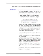
This section explains the replacement procedures for an
IISAC01 Analog Control Station. There are no special tools
required to replace an analog control station (SAC). Table
lists the recommended spare parts for the SAC station.
NOTE: Always use the Bailey field static kit (part number
1948385A1) when working with the station. This kit connects the
static dissipative work surface and technician to the same ground
point.
If you determine the SAC station is faulty, replace it with a new
one.
Do not
try to repair the station; replacing components
may affect the control loop performance. To replace a station:
1. If the station is in bypass or manual override mode, secure
control of the process prior to removing the station from a sys-
tem under power. The station in stand-alone or normal mode
can be removed from a system under power.
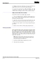
2. Use a straight blade screwdriver to turn the captive screw
located behind the legend door and release the station from its
housing.
3. Grasp the station faceplate at the left edge and pull the sta-
tion from its housing.
4. Set the replacement station display and operating options
(dipswitch and jumper settings). Insure that the replacement
station options are set the same as the options on the original
station. If you modify any of the options, record and date the
change in the space provided in each table of
5. Insert the replacement station in the station housing. Push
on the left edge of the faceplate until P1 on the SAC station cir-
cuit board seats in the cable connector at the rear of the hous-
ing.
6. Tighten the captive screw located behind the legend door
and lock the station in place.
7. Return to normal operation.
Table 7-1. Recommended Spare Parts List
Description
Part Number
Fuse, 1.0 A, 250 VDC
1948182A21001


