I-E96-416B
A - 1
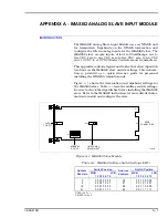
APPENDIX A - IMASI02 ANALOG SLAVE INPUT MODULE
INITRODUCTION
The IMASI02 Analog Slave Input Module uses an NTAI05 unit
for termination. Dipshunts on the NTAI05 termination unit
configure the fifteen analog inputs for the IMASI02 slave. The
IMASI02 slave accepts inputs of four to 20 milliamps, one to
five VDC, zero to one VDC, zero to five VDC, zero to ten VDC
and -10 VDC to +10 VDC (Bailey Controls smart transmitters).
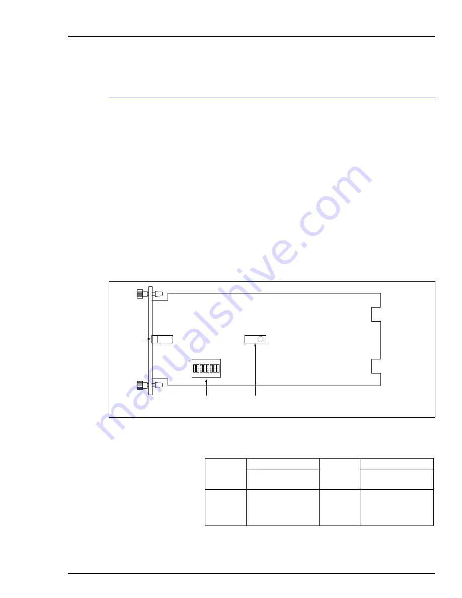
This appendix contains figures and tables that show dipswitch
locations on the IMASI02 slave and its settings. This informa-
tion is provided as a quick reference guide for personnel
installing the NTAI05 termination unit.
Figure
shows the termination unit dipshunt settings for
the IMASI02 slave. Table
lists the address switch settings.
Be sure to check the dipswitches before installing the IMASI02
slave. Refer to the IMASI02 instruction for more detailed infor-
mation to install and configure the slave.
Figure A-1. IMASI02 Slave Module
EDGE
CONNECTORS
ADDRESS
SWITCH
FINE-TUNING
ADJUSTMENT
JACK
FOR STT
P1
P3
P2
T00588A
S1
R22
1
OPEN
8
Table A-1. IMASI02 Address Switch Settings (SW1)
Address
Example
Switch Position
Address
Example
Switch Position
MSB
LSB
1 2 3 4 5 6 7 8
MSB
LSB
1 2 3 4 5 6 7 8
0
9
16
31
0 0 0 0 0 0 0 0
0 0 0 0 1 0 0 1
0 0 0 1 0 0 0 0
0 0 0 1 1 1 1 1
32
41
48
63
0 0 1 0 0 0 0 0
0 0 1 0 1 0 0 1
0 0 1 1 0 0 0 0
0 0 1 1 1 1 1 1
OPEN = OFF = 1
CLOSED = ON = 0

