Controller
98
Electrical Control System
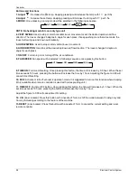
Buttons and functions
1. Adjust
: Decrease the set temp. Keeping pressing will decrease the temp with 1
℃
per 0.5s.
2. Adjust
: Increase the set temp. Keeping pressing will increase the temp with 1
℃
per 0.5s.
3. MODE
: Once pressing, running mode will be selected in the following sequence:
NOTE: No heating mode for cool only type unit.
4. VERT SWING:
Used to stop or start horizontal louver movement or set the desired up/down air flow
direction. The louver changes 6 degree in angle for each press. If keep pushing more than 2 seconds, the
louver will swing up and down automatically.
5. HORIZ SWING:
Used to stop or start vertical louver movement.
6. AIR DIRECTION
: Used to set the desired up/down air flow direction. The louver changes 6 degree in
angle for each press.
7. ON/OFF
: For turning on or turning off the air conditioner.
8. FAN SPEED:
Fan speed will be selected in following sequence once pressing this button:
9. TIME ON:
For time ON setting. Once pressing this button, the time will increase by 0.5 hour. When the set
time exceeds 10 hours, pressing the button will increase the time by 1 hour. Adjusting the figure to 0.00 will
cancel time ON setting.
10. ECO:
Activate or turn off economic operation mode. It is suggested to turn on this function when sleeping.
(Only available when remote controller is used with corresponding unit.)
11. TIME OFF:
For time OFF setting. Once pressing this button, the time will increase by 0.5 hour. When the
set time exceeds 10 hours, pressing the button will increase the time by 1 hour.
Adjust the figure to 0.00 will cancel time ON setting.
12. C/H
(inner located): Press this button with a needle of 1mm to shift the mode between Cooling only and
Cooling & Heating according to the feature of the machine.
13.RESET
(inner located): Press this button with a needle of 1mm to cancel the current setting and reset
remote controller.
AUTO
COOL
DRY
HEAT
FAN
AUTO
LOW
MED
HIGH
Summary of Contents for BSBSI36CTM
Page 5: ...External Appearance General Information 3 2 External Appearance 2 1 Indoor Units Duct ...
Page 15: ...Wiring Diagrams 13 4 Wiring Diagrams BSBSIE36CTM BSBSIE48CTM BSBSIE60CTM ...
Page 22: ...Field Wiring 20 Duct Type 10 Field Wiring ...
Page 25: ...Dimensions 23 Outdoor Units Model Unit mm W D H W1 A B BSBSIC60CTM 952 415 1333 1045 634 404 ...
Page 28: ...Wiring Diagrams 28 Outdoor Units 4 Wiring Diagrams BSBSIC36CTM BSBSI48CTM BSBSIC60CTM ...
Page 42: ...Installation Installation 43 ...
Page 82: ...Troubleshooting Electrical Control System 85 ...


