background image


Controller 

Electrical Control System 

99 


3.1.2 RG51C/E 

Remote Controller Specifications


Model 

RG51C/E 

Rated Voltage 

3.0V 

Lowest Voltage of CPU Emitting Signal 

2.0V 

Reaching Distance 

8m (when using 3.0 voltage, it can get 11m) 

Environment Temperature Range 

-5

60


Introduction of Function Buttons on the Remote Controller


ADJUST

AUTO 
COOL

DRY
HEAT

FAN
HIGH

MED
LOW

MODE

SWING

FAN SPEED

TIMER ON

ECO

ON/OFF

TIMER OFF

RESET LOCK

2

1

4

5

3

7

8

9

10

11

SET TEMPERATURE(   C)

12

Adjust

Mode setting

Adjust

ON/OFF

TIMER  ON

TIMER  OFF

Lock

Economic operation

Fan speed setting

SWING

   AIR

DIRECTION 

Reset

13


1. Adjust 

  : Decrease the set temp. Keeping pressing will decrease the temp with 1

  per 0.5s. 

2. Adjust 

: Increase the set temp. Keeping pressing will increase the temp with 1

  per 0.5s. 

3. MODE

: Once pressing, running mode will be selected in the following sequence:   


NOTE: No heating mode for cool only type unit.   

4. VERT SWING:

 Used to stop or start horizontal louver movement. The louver will swing up and down   

automatically if push this button. 

AIR DIRECTION

: Used to set the desired up/down air flow direction. The louver changes 6 degree in   

angle for each press. 

5. HORIZ SWING:

 Used to stop or start vertical louver movement.   

6. FAN SPEED+ MODE

: Press the Mode and Fan speed button simultaneously for 2 seconds. The remote   

AUTO

COOL

DRY

HEAT

FAN

Summary of Contents for BSBSI36CTM

Page 1: ...nstrucciones Baja Silueta Inverter Lea atentamente todo este manual antes de utilizar su nuevo equipo de aire acondicionado Modelos DC Series BSBSI36CTM BSBSI48CTM BSBSI60CTM IMPRESO EN PAPEL ECOLÓGICO Rev 28AGO17 ...

Page 2: ...ion 1 Part 2 Indoor Units 7 Part 3 Outdoor Units 22 Part 4 Installation 33 Part 5 Electrical Control System 53 The specifications designs and information in this book are subject to change without notice for product improvement ...

Page 3: ...General Information General Information 1 Part 1 General Information 1 Model Lists 2 2 External Appearance 3 2 1 Indoor Units 3 2 2 Outdoor Units 4 3 Nomenclature 5 4 Features 6 ...

Page 4: ...ion 12 18 24 30 36 48 60 High static pressure duct Cooling and heating 1 2 Outdoor Units Universal Outdoor unit Model Compressor type Compressor Brand Matched indoor units BSBSIC36CTM Rotary DC Inverter GMCC BSBSIE36CTM BSBSIC48CTM Rotary DC Inverter BSBSIE48CTM BSBSIC60CTM Rotary DC Inverter BSBSIE60CTM GMCC GMCC ...

Page 5: ...External Appearance General Information 3 2 External Appearance 2 1 Indoor Units Duct ...

Page 6: ...External Appearance 4 General Information 2 2 Outdoor Units Single fan outdoor unit Double fan outdoor unit ...

Page 7: ...Nomenclature General Information 5 3 Nomenclature 3 1 Indoor Unit 3 2 Outdoor Unit B M BS I E 24 C T M B M BS I C 24 C T M ...

Page 8: ...or more choice for you 4 4 Low ambient kit is standard for outdoor units except 12K 4 5 Network control function is standard for the indoor units except 12K 4 6 Standard auto restart function and follow me function 4 7 Cassette ceiling floor console and compact cassette with standard remote controller wire controller and CCM for optional Med Duct with standard wired controller remote controller an...

Page 9: ...o con el estilo especificado en el documento 7 Part 2 Indoor Units Duct Type 1 Features 8 2 Dimensions 11 3 Service Space 12 4 Wiring Diagrams 13 5 Static Pressure 14 6 Electric Characteristics 16 7 Sound Levels 17 8 Accessories 18 9 The Specification of Power 19 10 Field Wiring 20 ...

Page 10: ...to the bottom in order to matching the installation condition 1 3 Easy maintenance Clean the filter Optional standard product without filter It is easy to draw out the filter from the indoor unit for cleaning even the filter is installed in rear side or bottom side Front Board Canvas Air Passage Filter Standard Panel Standard Air intake from rear Standard Air intake from bottom Optional Replace th...

Page 11: ... controller or a central controller to realize remote on off control function or group control function 1 5 Built in drain pump Optional Built in drain pump can lift the water to 750mm upmost It s convenient to install drainage piping under most space condition Motor Blower Housing Ventilated Panel Remote on off ports Central control ports 750mm upmost ...

Page 12: ...board with a receiver in the E box Move out the display and fix it in other place even in the distance of 10m The unit will realized remoter control The wired controller and the display board can display the error code or production code when the chips detect some failure Display Wired Controller Optional Remote Controller Standard ...

Page 13: ...ke 25 Drain pipe 25 Drain pipe Unit mm Model Btu h Outline dimension mm Air outlet opening size Air return opening size Size of install hanger Size of refrigerant pipe A B C D E F G H I J K L M H1 H2 W1 W2 18K 920 210 635 570 65 713 35 119 815 200 80 960 350 120 143 95 150 24K 920 270 635 570 65 713 35 179 815 260 20 960 350 120 143 95 150 36K 1140 270 775 710 65 933 35 179 1035 260 20 1240 500 12...

Page 14: ...Service Space 12 Duct Type 3 Service Space Ensure enough space required for installation and maintenance ...

Page 15: ...Wiring Diagrams 13 4 Wiring Diagrams BSBSIE36CTM BSBSIE48CTM BSBSIE60CTM ...

Page 16: ...0 500 1000 1500 2000 2500 0 10 20 30 40 90 100 110 120 130 Air flow rate m3 h 50 60 70 80 External static pressure Pa 36K 0 500 1000 1500 2000 2500 3000 0 10 20 30 40 90 100 110 120 130 Air flow rate m3 h 50 60 70 80 External static pressure Pa 48K ...

Page 17: ...Static Pressure 15 0 500 1000 1500 2000 2500 3000 0 10 20 30 40 90 100 110 120 130 Air flow rate m3 h 50 60 70 80 External static pressure Pa 60K ...

Page 18: ...Electric Characteristics 16 Duct Type 6 Electric Characteristics Model Indoor Unit Hz Voltage Min Max BSBSIE36CTM 50 220 240 198 254 BSBSIE48CTM 50 220 240 198 254 BSBSIE60CTM 50 220 240 198 254 ...

Page 19: ...Sound Levels 17 7 Sound Levels Suction Discharge Microphone 1 4m Concealed Duct Type Duct Duct Model Noise level dB A H M L BSBSIE36CTM 48 44 38 BSBSIE48CTM 48 42 39 BSBSIE60CTM 49 44 42 ...

Page 20: ... Fittings Name Shape Quantity Soundproof insulation sheath 2 Binding tape 1 Seal sponge 1 Drainpipe Fittings for cooling heating Drain joint 1 Seal ring 1 Wired controller Its Frame Wired controller 1 Others Owner s manual 1 Installation manual 1 ...

Page 21: ...EAKER FUSE A 15 10 OUTDOOR UNIT POWER Phase 3 phase Frequency and Voltage 380 415V 50Hz CIRCUIT BREAKER FUSE A 30 20 48000Btu h 1 phase 220 240V 50Hz 15 10 3 phase 30 25 380 415V 50Hz 60000Btu h 1 phase 220 240V 50Hz 15 10 3 phase 30 25 380 415V 50Hz Outdoor unit power wiring 3 2 5 5 2 5 5 2 5 Strong electric signal 4 1 0 4 1 0 4 1 0 Weak electric signal ...

Page 22: ...Field Wiring 20 Duct Type 10 Field Wiring ...

Page 23: ...Outdoor Units 21 Outdoor Units Part 3 Outdoor Units 1 Dimensions 23 2 Service Space 26 3 Piping Diagrams 27 4 Wiring Diagrams 28 5 Electric Characteristics 30 6 Operation Limits 31 7 Sound Levels 32 ...

Page 24: ...Dimensions Outdoor Units 22 1 Dimensions Model Unit mm W D H W1 A B BSBSIC36CTM 946 410 810 1030 673 403 BSBSIC48CTM 946 410 810 1030 673 403 W H W1 A B D ...

Page 25: ...Dimensions 23 Outdoor Units Model Unit mm W D H W1 A B BSBSIC60CTM 952 415 1333 1045 634 404 ...

Page 26: ...Service Space 24 Outdoor Units 2 Service Space More than 60cm More than 30cm More than 60cm More than 200cm Air inlet Air inlet More than 30cm Air outlet Wall or obstacle Maintain channel ...

Page 27: ...SIDE GAS SIDE HEAT EXCHANGE EVAPORATOR HEAT EXCHANGE CONDENSER Compressor 2 WAY VALVE 3 WAY VALVE 4 WAY VALVE COOLING HEATING T2 Evaporator temp sensor T1 Room temp sensor Accumulator T5 Discharge temp sensor High pressure switch Low pressure switch INDOOR OUTDOOR T3 Condenser temp sensor T4 Ambient temp sensor ...

Page 28: ...Wiring Diagrams 28 Outdoor Units 4 Wiring Diagrams BSBSIC36CTM BSBSI48CTM BSBSIC60CTM ...

Page 29: ...tdoor Units 5 Electric Characteristics Model Outdoor Units Power Supply Hz Voltage Min Max MFA 50 380 415V 342V 440V 20 50 380 415V 342V 440V 25 50 380 415V 342V 440V 25 Notes MFA Max Fuse Amps A BSBSIC36CTM BSBSIC48CTM BSBSIC60CTM ...

Page 30: ...s used beyond the above conditions certain safety protection features may come into operation and cause the unit to operate abnormally 2 The room relative humidity should be less than 80 If the air conditioner operates beyond this figure the surface of the air conditioner may attract condensation Please set the vertical air flow louver to its maximum angle vertically to the floor and set HIGH fan ...

Page 31: ...Sound Levels 31 Outdoor Units 7 Sound Levels Note H 0 5 height of outdoor unit Model Noise level dB A H BSBSIC36CTM 62 BSBSIC48CTM 65 H 1 0m Outdoor Unit Microphone BSBSIC60CTM 66 ...

Page 32: ...oor unit installation 36 4 Outdoor unit installation Side Discharge Unit 39 5 Refrigerant pipe installation 40 6 Drainage pipe installation 44 7 Vacuum Drying and Leakage Checking 48 8 Additional refrigerant charge 49 9 Engineering of insulation 50 10 Engineering of electrical wiring 51 11 Test operation 52 ...

Page 33: ... Wiring connection and electric safety checking Test operation Refrigerant pipe installation and insulation Drainage pipe installation and insulation Indoor unit installation location selection Outdoor unit installation location selection Indoor unit installation Outdoor unit installation Refrigerant pipe installation and insulation Drainage pipe installation and insulation ...

Page 34: ...The place shall easily support the outdoor unit s weight Locate the outdoor unit as close to indoor unit as possible The piping length and height drop can not exceed the allowable value The place where the noise vibration and outlet air do not disturb the neighbors There is enough room for installation and maintenance The air outlet and the air inlet are not impeded and not face the strong wind It...

Page 35: ...t installation 3 3 1 Service space for indoor unit 3 3 2 Bolt pitch 3 3 3 Install the pendant bolt Select the position of installation hooks according to the hook holes positions showed in upper picture Capacity KBtu Size of outline dimension mounted plug L M 36 1240 500 48 60 1240 500 ...

Page 36: ... the 4 hanger of the main body to suspend it Adjust the hexangular nuts on the four installation hooks evenly to ensure the balance of the body Use a leveling instrument to make sure the levelness of the main body is within 1 3 3 5 Install the air filter Insert the air filter through the filter slot and fix it with 2 screws 3 3 6 Install the air duct Please design the air duct as below recommended...

Page 37: ...d seal sponge as per the indicating place in the following fig and then change the mounting positions of air return panel and air return flange When install the filter mesh please plug it into flange inclined from air return opening and then push up The installation has finish upon filter mesh which fixing blocks have been insert to the flange positional holes ...

Page 38: ... it from deforming Do not touch the fan with hands or other objects Do not lean it more than 45 and do not lay it sidelong Make concrete foundation according to the specifications of the outdoor units Fasten the feet of this unit with bolts firmly to prevent it from collapsing in case of earthquake or strong wind More than 60cm More than 30cm More than 60cm More than 200cm Air inlet Air inlet More...

Page 39: ...u h 36 000 Btu h 30m 20m 42 000Btu h 60 000Btu h 50m 30m 5 2 The procedure of connecting pipes 5 2 1 Choose the pipe size according to the specification table 5 2 2 Confirm the cross way of the pipes 5 2 3 Measure the necessary pipe length 5 2 4 Cut the selected pipe with pipe cutter Make the section flat and smooth 9 0 Lean Crude Burr o 5 2 5 Insulate the copper pipe Before test operation the joi...

Page 40: ...d fix it by supporter For horizontal refrigerant pipe the distance between supporters should not be exceed 1m For vertical refrigerant pipe the distance between supporters should not be exceed 1 5m 5 2 13 Connect the pipe to indoor unit and outdoor unit by using two spanners Be sure to use two spanners and proper torque to fasten the nut too large torque will damage the bellmouthing and too small ...

Page 41: ... 18K 18K 30m L L1 L2 24K 24K 50m 30K 30K 50m Max branch pipe length 15m L1 L2 Max branch pipe length difference 10m L1 L2 Drop Height Max height difference between indoor unit and outdoor unit 20m H1 Max height difference between indoor units 0 5m H2 5 3 2 Size of joint pipes for indoor unit R410a 5 3 3 Size of joint pipes for outdoor unit R410a 5 3 4 The branching pipe must be installed horizonta...

Page 42: ...Installation Installation 43 ...

Page 43: ...ter flowrate is decided by the capacity of indoor unit Relationship between water flowrate and capacity of indoor unit Capacity x1000Btu Water flowrate l h 12 2 4 18 4 24 6 30 7 36 8 42 10 48 12 60 14 According to the above table to calculate the total water flowrate for the confluence pipe selection For horizontal drainage pipe The following table is for reference PVC pipe Reference value of inne...

Page 44: ...ance Gas bag 6 2 5 The horizontal pipe layout should avoid converse flow or bad flow Drainage pipe Water flow Drainage pipe Drainage pipe Drain tee Drain tee Water flow Water flow Water flow Water flow Water flow Water flow Water flow Water flow Drain tee Branch pipe Water flow Water flow Keep a certain degree Branch pipe Gas Gas Main pipe Main pipe The correct installation will not cause converse...

Page 45: ...ch Refer the following picture for installation reference Flexible pipe 300mm Hanger A A Length of horizontal pipe 150mm B Lift height the pump head of water pump Down incline pipe B 6 2 8 Blowhole setting For the concentrated drainage pipe system there should design a blowhole at the highest point of main pipe to ensure the condensate water discharge smoothly The air outlet shall face down to pre...

Page 46: ...nage outlet In light of the length of drainage pipe water shall be discharged about 1 minute delayed 2 3 Stop the operation of air conditioner power off the power supply and put the cover of water test hole back to the original place a After stopped the air conditioner 3 minutes check whether there is anything abnormal If drainage pipes have not been distributed properly over back flow water shall...

Page 47: ...mHg after 1 5 hours of drying check whether there is leakage source 4 Leakage test After the vacuum degree reaches 755mmHg stop vacuum drying and keep the pressure for 1 hour If the indicator of vacuum gauge does not go up it is qualified If going up it indicates that there is moisture or leak source 7 3 2 Special vacuum drying The special vacuum drying method shall be adopted when 1 Finding moist...

Page 48: ...efrigerant may only be charged after performed the vacuum drying process Always use gloves and glasses to protect your hands and eyes during the charge work Use electronic scale or fluid infusion apparatus to weight refrigerant to be recharged Be sure to avoid extra refrigerant charged it may cause liquid hammer of the compressor or protections Use supplementing flexible pipe to connect refrigeran...

Page 49: ... environment place the layer of insulation should be thicker accordingly 9 1 4 Installation highlights of insulation construction Gas pipe and liquid pipe shall be insulated separately if the gas pipe and liquid pipe were insulated together it will decrease the performance of air conditioner Liquid pipe Insulation meterial Gas pipe The insulation material at the joint pipe shall be 5 10cm longer t...

Page 50: ... construction should be finished by qualified electrician Air conditioning equipment should be grounded according to the local electrical regulations Current leakage protection switch should be installed Do not connect the power wire to the terminal of signal wire When power wire is parallel with signal wire put wires to their own wire tube and remain at least 300mm gap According to table in indoo...

Page 51: ...units The gas side and liquid side stop values are both opened The air conditioner is pre heated by turning on the power 11 3 Test operation Set the air conditioner under the mode of COOLING by remote controller and check the following points Indoor unit Whether the switch on the remote controller works well Whether the buttons on the remote controller works well Whether the air flow louver moves ...

Page 52: ...Electrical Control System Electrical Control System 53 Part 5 Electrical Control System 1 Electrical Control Function 54 2 Troubleshooting 69 3 Controller 97 ...

Page 53: ...1 or 2 phase the unit won t start and there is error code displayed on outdoor PCB 1 2 4 Temperature protection of compressor discharge When the compressor discharge temp is getting higher the running frequency will be limited as below rules 18 24K 36 60K T5 Compressor off Frequency limit Normal Frequency holding 1 2 5 Low pressure check function for 36 60K models The low pressure switch should be...

Page 54: ...gh med low auto 4 The louver operates same as in cooling mode 5 Auto fan 27 5 T1 27 High Low 25 Medium 25 5 5 0 T1 24 4 0 High Low 2 0 Medium 3 0 1 3 2 Cooling Mode 1 3 2 1 Outdoor PMW open angle control The unit is working in cooling mode with the EXV open 300P for 3 minutes then adjusting PMW open angle according to the temperature of compressor discharge every 2 minutes 1 3 2 2 Outdoor fan runn...

Page 55: ...nning for 1 minute 1 3 2 3 Indoor fan running rules In cooling mode indoor fan runs all the time and the speed can be selected as high medium low and auto The auto fan 4 T1 Ts 3 High Low 1 Medium 1 5 Setting fan speed Actual fan speed H H H G A H H B C M M M Z D M M M E F L L L D G L L L H I T1 Td F L L L L D H H H H G M M M M Z The auto fan acts as below rules T1 Ts High Low Medium ...

Page 56: ...mperature T3 protection When T3 65 for 3 seconds the compressor will shut off When T3 52 the compressor will restart 1 3 3 Heating Mode 1 3 2 1 Outdoor PMW open angle control The unit is working in heating mode with the EXV open 300P for 3 minutes then adjusting PMW open angle according to the temperature of compressor discharge every 2 minutes 1 3 3 2 Outdoor fan running rules T2 On 30 36K T3 Res...

Page 57: ...door fan can be set to high med low auto And the anti cold wind function has the priority Auto fan action Frequency linkage area Frequency of compressor operation Low High 36 60K T4 Low High Setting fan speed Actual fan speed H H H H H G M M M M M M Z L L L L L L D H H H G M M M Z L L L D T1 Td L H M T1 Ts High Low Medium ...

Page 58: ...time Condition of ending defrosting If any one of the following items is satisfied the defrosting will finish and the machine will turn to normal heating mode T3 rises to be higher than TCDE1 T3 keeps to be higher than TCDE2 for 80 seconds The machine has run for 15 minutes 18 24K or 10 minutes 36 60k in defrosting mode no longer than 10min 60s on 10s F8 30s Compressor F2 off 4 way valve on off Ou...

Page 59: ... valve Indoor fan Outdoor fan 480P PMV PMV running 6 mins with 300P Compressor 10S 30S TimeA 10S no longer than 10min Condition of ending defrosting If any one of following items is satisfied defrosting will stop and the machine will turn to normal heating mode T3 TempQuitDefrost_ADD The defrosting time achieves 10min For 48K 1 Phase 36 60K 3 Phase models Condition of defrosting ...

Page 60: ... Compressor is off 2 T3 TempEnterDefrost_ADD Time2 Time conditions Meet the following conditions 1 Running in heating mode 2 T4 3 3 Compressor is on 4 T3 TempEnterDefrost_ADD Cleared conditions Meet any one of the following conditions 1 Compressor is off and T3 TempEnterDefrost_ADD 2 last for 20 minutes 2 Running in cooling mode 3 Compressor is off for 1 hour Condition of entry defrosting time1 ti...

Page 61: ...e will turn to normal heating mode The defrosting time achieves 10min T3 15 T3 7 for 60seconds 1 3 3 5 High evaporator coil temp T2 protection T2 60 the compressor will stop and restart when T2 54 1 3 4 Auto mode This mode can be chosen with remote controller and the setting temperature can be changed between 17 30 In auto mode the machine will choose cooling heating or fan only mode according to ...

Page 62: ... high temperature protection and outdoor unit frequency limit are active and the same as that in cooling mode For other models Drying mode works the same as cooling mode in low speed All protections are active and the same as that in cooling mode 1 3 6 Timer function 1 3 6 1 Timing range is 24 hours 1 3 6 2 Timer on The machine will turn on automatically when reaching the setting time 1 3 6 3 Time...

Page 63: ...tting temperature rises 1 be lower than 30 every one hour 2 hours later the setting temperature stops rising and the indoor fan is fixed at low speed When heating the setting temperature decreases 1 be higher than 17 every one hour 2 hours later the setting temperature stops rising and indoor fan is fixed at low speed Anti cold wind function has the priority 1 3 7 3 Operation time in sleep mode is...

Page 64: ...m and the drain pump open and continue checking the water level If the water level fall down and LED disalarmed drain pump delay close 1 minute and operate with the last mode Otherwise the entire system stop operating including the pump and LED remain alarming after 3 minutes 1 3 10 Point Check Function Except 12k models There is a check switch in outdoor PCB Press the switch SW1 to check the stat...

Page 65: ... open angle Actual data 4 If the value is higher than 99 the digital display tube will show single digit and tens digit For example the digital display tube show 2 0 it means the EXV open angle is 120 4 480p 15 Frequency limit symbol Bit7 Frequency limit caused by IGBT radiator The display value is hex number For example the digital display tube show 2A then Bit5 1 Bit3 1 Bit1 1 It means frequency...

Page 66: ... than 99 the digital display tube will show single digit and tens digit For example the digital display tube show 5 0 it means the capacity demand is 15 the digital display tube show 60 it means the capacity demand is 6 0 If the indoor unit is not connected the digital display tube will show 24 3 Indoor unit capacity demand code ...

Page 67: ...lanation on indoor display board A5 Duct High static pressure Duct OPERATION TIMER DEF FAN ALARM Temporary button Operation lamp Timer indicator Infrared signal receiver Alarm indicator PRE DEF indicator cooling and heating type or fan only indicator cooling only type MANUAL Display digital tube ...

Page 68: ...ld communication protocol Ed X 11 Overcurrent protection For some units F0 O 1 Open or short circuit of T4 temperature sensor F1 O 2 Open or short circuit of T3 temperature sensor F2 O 3 Open or short circuit of T5 temperature sensor F3 O 4 Outdoor EEPROM malfunction For some units F4 O 5 Communication error between auto lifting panel and slim cassette For slim cassette with auto lifting panel F7 ...

Page 69: ...on malfunction between IPM board and outdoor main board E4 Open or short circuit of T3 or T4 temperature sensor E5 Voltage protection of compressor E6 PFC module protection Only for 36K 48K with 1 phase P0 Top temperature protection of compressor P1 High pressure protection Only for 30K 60K P2 Low pressure protection Only for 30K 60K P3 Current protection of compressor P4 Discharge temperature pro...

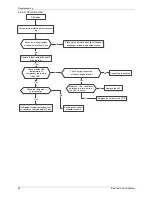
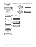
Page 70: ...the indoor PCB Replace the indoor PCB Measure the resistance value of the sensor via Appendix 1 Measure the resistance value of the sensor via Appendix 1 Is it normal Is it normal Yes 2 4 1 2 Outdoor unit malfunction Whether the outdoor main board has error displayed Whether the outdoor main board has error displayed Power off then restart the unit 2 minutes later If the outdoor main board display...

Page 71: ...witch is inserted well No Insert the water level switch well Insert the water level switch well If the water level switch is broken If the water level switch is broken Yes Replace the water level switch Replace the water level switch Replace the water pump If malfunction is still not solved Replace the water pump If malfunction is still not solved Yes No Yes Replace the indoor main PCB Replace the...

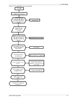
Page 72: ...crews which fix the fan are tighten Check the wiring of fan motor Are all the connections good Check the wiring of fan motor Are all the connections good No Yes No Correct the connections Correct the connections No Replace the fan motor Replace the fan motor Yes Yes Replace the main PCB Replace the main PCB No Check whether the main PCB is normal through index 1 Check whether the main PCB is norma...

Page 73: ...connection No Yes Replace the indoor main PCB Replace the indoor main PCB No Replace the up down panel Replace the up down panel 2 4 2 2 Up down panel is defective F1 Displayed F1 Displayed Up down panel is defective Up down panel is defective Retry if panel can up and down normally Retry if panel can up and down normally Check the wiring of left and right sensors Check the wiring of left and righ...

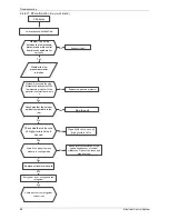
Page 74: ...s No Check the PQE communication wires connection is it good enough Check the PQE communication wires connection is it good enough Yes Correct the wire connections Correct the wire connections No One of the 2 indoor PCBs is defective Connect only one indoor unit to the outdoor unit separately The one caused E1 error code is defective One of the 2 indoor PCBs is defective Connect only one indoor un...

Page 75: ...ews and apply silicon grease No Check if the outdoor fan can run properly Yes No Correct the connection of fan motor or replace the fan motor Yes Replace outdoor control PCB Does the problem still remain Replace the compressor Yes 2 4 4 2 E0 malfunction EEPROM An electrically erasable programmable read only memory whose contents can be erased and reprogrammed using a pulsed voltage Outdoor EEPROM ...

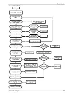
Page 76: ...oor main PCB Power on Is the error extinguished Replace the outdoor main PCB Power on Is the error extinguished Check the outdoor wiring connection Check the outdoor wiring connection Replace the indoor main PCB Power on Is the error extinguished Replace the indoor main PCB Power on Is the error extinguished Yes Replace the outdoor main PCB Replace the outdoor main PCB No Replace the indoor main P...

Page 77: ... No No Replace indoor main PCB is the error distinguished Replace indoor main PCB is the error distinguished Yes Replace the outdoor Main PCB Replace the outdoor Main PCB No Check whether there s any interference Such as too many lamps power transformers Or the signal wire is too long Check whether there s any interference Such as too many lamps power transformers Or the signal wire is too long Ch...

Page 78: ...d light Check the signal wire between the IPM board and the main board is it connected good Reconnect and retry Is error still display Replace IPM board and then check whether the system can run normally Replace the electric control box No No No No Yes Trouble is solved No Yes Replace outdoor main board and then check whether the system can run normally No Yes Yes E3 display ...

Page 79: ...nt temperature sensor T4 is broken off Check whether the wiring of the outdoor ambient temperature sensor T4 is broken off Check whether the resistance of outdoor ambient temperature sensor T4 is wrong refer to the Appendix 1 Check whether the resistance of outdoor ambient temperature sensor T4 is wrong refer to the Appendix 1 Yes Connect the wiring well Connect the wiring well Yes Judge 3 Compres...

Page 80: ...bridge rectifier is normal Yes No No Measure whether the voltage between P and N is normal refer to the Appendix 3 Measure whether the voltage between P and N is normal refer to the Appendix 3 Replace the bridge rectifier Replace the bridge rectifier No Check whether bridge rectifier is normal Check whether bridge rectifier is normal Check the wiring of reactor or inductance Check the wiring of re...

Page 81: ...the PFC module is connected tightly Yes Measure whether the voltage between P and N is normal refer to the Appendix 3 No Check whether the inductance of PFC module is good If the inductance is good the resistance of the two ports is 0 Yes Replace the inductance No Connect it tightly check normal or not Replace the outdoor main board Yes Yes No No Replace the PFC module Trouble is solved ...

Page 82: ...Troubleshooting Electrical Control System 85 ...

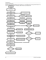
Page 83: ...Check the refrigerant volume charge Check the refrigerant volume charge Recharge the correct refrigerant volume Recharge the correct refrigerant volume Refrigerant system is blocked such as capillary or welded point of pipes Refrigerant system is blocked such as capillary or welded point of pipes Yes Check wiring connection of the overload protector Check wiring connection of the overload protecto...

Page 84: ...ent temperature is higher than 50 Check whether the outdoor ambient temperature is higher than 50 No Stop the unit Stop the unit Yes Check if the outdoor unit ventilation is good Check if the outdoor unit ventilation is good Yes Make the outdoor unit ventilate well Make the outdoor unit ventilate well Check whether the heat exchanger is dirty Check whether the heat exchanger is dirty No Clean the ...

Page 85: ...hether the low pressure protector is broken Whether the low pressure protector is broken Check whether the outdoor ambient temperature is too low Check whether the outdoor ambient temperature is too low No Stop the unit Stop the unit Yes Open fully valve core of high pressure valve Open fully valve core of high pressure valve No Check whether valve core of high pressure valve is opened Check wheth...

Page 86: ...ormal refer to the Appendix 3 Measure whether the voltage between P and N is normal refer to the Appendix 3 Replace the bridge rectifier Replace the bridge rectifier No Check whether bridge rectifier is normal Check whether bridge rectifier is normal Check the wiring of reactor or inductance Check the wiring of reactor or inductance Reconnect the wiring Reconnect the wiring No Check whether reacto...

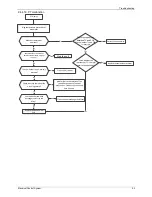
Page 87: ...r the connection is right between compressor discharge temp sensor and PCB according to wiring diagrams M easure the resistance value of compressor discharge temp sensor If the value is not normal is normal refer to the Appendix 2 M easure the resistance value of compressor discharge temp sensor If the value is not normal is normal refer to the Appendix 2 No Yes Yes No Correct the wiring connectio...

Page 88: ...if the outdoor unit ventilation is good Check if the outdoor unit ventilation is good Yes Make the outdoor unit ventilate well Make the outdoor unit ventilate well Check whether the heat exchanger is dirty Check whether the heat exchanger is dirty No Clean the heat exchanger Clean the heat exchanger Yes Check whether the refrigerant system is ok Check whether the refrigerant system is ok Replace o...

Page 89: ...to the Appendix 3 Replace the bridge rectifier Replace the bridge rectifier No Check whether bridge rectifier is normal Check whether bridge rectifier is normal Check the wiring of reactor or inductance Check the wiring of reactor or inductance Reconnect the wiring Reconnect the wiring No Check whether reactor or inductance is normal Check whether reactor or inductance is normal Yes Replace reacto...

Page 90: ...istance of T2 is normal refer to the Appendix 1 Replace the temperature sensor Replace the temperature sensor No Yes Yes Stop the unit Stop the unit Yes Check whether the air outlet is blocked Check whether the air outlet is blocked Check whether the heat exchanger and filter are dirty Check whether the heat exchanger and filter are dirty Check whether the indoor fan is running normal Check whethe...

Page 91: ... 6 13059 76 1 34105 116 0 40060 3 41 5878 37 5 87359 77 1 29078 117 0 38991 2 39 8239 38 5 62961 78 1 25423 118 0 37956 1 37 1988 39 5 39689 79 1 21330 119 0 36954 0 35 2024 40 5 17519 80 1 17393 120 0 35982 1 33 3269 41 4 96392 81 1 13604 121 0 35042 2 31 5635 42 4 76253 82 1 09958 122 0 3413 3 29 9058 43 4 57050 83 1 06448 123 0 33246 4 28 3459 44 4 38736 84 1 03069 124 0 32390 5 26 8778 45 4 21...

Page 92: ...489 5 234 9 35 35 78 75 8 084 115 2 422 4 222 8 36 34 32 76 7 82 116 2 357 3 211 4 37 32 94 77 7 566 117 2 294 2 200 7 38 31 62 78 7 321 118 2 233 1 190 5 39 30 36 79 7 086 119 2 174 0 180 9 40 29 15 80 6 859 120 2 117 1 171 9 41 28 81 6 641 121 2 061 2 163 3 42 26 9 82 6 43 122 2 007 3 155 2 43 25 86 83 6 228 123 1 955 4 147 6 44 24 85 84 6 033 124 1 905 5 140 4 45 23 89 85 5 844 125 1 856 6 133 ...

Page 93: ...ix 3 Normal voltage of P and N 208 240V 1 phase 3 phase 380 420V 3 phase In standby around 310VDC around 530VDC In operation With passive PFC module With partial active PFC module With fully active PFC module 200VDC 310VDC 370VDC 450VDC ...

Page 94: ...Wireless Remote Controller 3 1 1RG51Q1 BGE General Function for wireless remote controller Model RG51Q1 BGE Rated voltage 3 0V 2pieces of LR03 7 batteries Min voltage for sending signal of CPU 2 4V Effective receiving distance 8m 11m Operation condition 5 60 ...

Page 95: ...SPEED Fan speed will be selected in following sequence once pressing this button 9 TIME ON For time ON setting Once pressing this button the time will increase by 0 5 hour When the set time exceeds 10 hours pressing the button will increase the time by 1 hour Adjusting the figure to 0 00 will cancel time ON setting 10 ECO Activate or turn off economic operation mode It is suggested to turn on this...

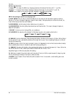
Page 96: ...eedsetting SW IN G AIR DIRECT IO N R ese t 13 1 Adjust Decrease the set temp Keeping pressing will decrease the temp with 1 per 0 5s 2 Adjust Increase the set temp Keeping pressing will increase the temp with 1 per 0 5s 3 MODE Once pressing running mode will be selected in the following sequence NOTE No heating mode for cool only type unit 4 VERT SWING Used to stop or start horizontal louver movem...

Page 97: ...ile the unit is running under Energy saving mode it would be cancelled if press MODE FAN SPEED or ON OFF button 11 TIME OFF For time OFF setting Once pressing this button the time will increase by 0 5 hour When the set time exceeds 10 hours pressing the button will increase the time by 1 hour Adjust the figure to 0 00 will cancel time ON setting 12 LOCK inner located Push this button to lock in al...

Page 98: ... swing angle of the louver The swing angle of the louver is 6o for each press When the louver swing at a certain angle which would affect the cooling and heating effect of the air conditioner it would automatically change the swing direction No symbol will appear in the display area when press this button Not applicable to units without this function 7 LED Press this button to clear the digit disp...

Page 99: ...inner located Push this button to lock in all the current settings and the remote controller will not accept any operation except that of the LOCK Use the LOCK mode when you want to prevent settings from being changed accidentally Press the LOCK button again to cancel the LOCK function A lock symbol will appear on the remote controller display when the lock function is activated 14 TURBO Push this...

Reviews: